Power cable laying device

A power cable and sliding rod technology, which is applied in the field of power cable laying devices, can solve problems such as cable surface wear, cable winding chaos, and affecting the service life of cables, and achieve the effect of ensuring service life

Inactive Publication Date: 2017-02-22
STATE GRID SHANDONG ELECTRIC POWER CO LONGKOU POWER SUPPLY CO
View PDF11 Cites 2 Cited by
  • Summary
  • Abstract
  • Description
  • Claims
  • Application Information

AI Technical Summary

Problems solved by technology

[0002] In the process of cable laying, in order to facilitate maintenance and adjustment, some margin is often left, especially for buried cable laying, extra cables will be reserved in the fixed area, because the outside of the cable is usually set Anti-corrosion, anti-insect and other protective layer structure, the existing way of directly winding the cable is easy to cause confusion in the winding of the cable, and the surface of the cable is prone to wear and tear, which affects the service life of the cable

Method used


Image

  • Power cable laying device

Examples


Embodiment 1

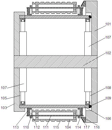
[0021] This embodiment discloses a preferred structure of a sliding rod. Preferably, two sets of beams 110 are arranged on the sliding rod 106, and the two sets of beams are symmetrically arranged on the sliding rod. Crossbar structure, the axis of the crossbeam 110 is perpendicular to the axis of the sliding rod 106, that is, the axis of each crossbar is perpendicular to the length direction of the sliding rod, and the two groups of crossbeams 110 are respectively provided with rotating shafts 111, so that the two groups of rotating shafts Parallel to each other, the rotating shafts 111 are parallel to the sliding rod 106, and the two rotating shafts 111 are symmetrically arranged on the side of the sliding rod 106 away from the central axis 102 respectively. By setting two sets of rotating shafts, the When the cable touches the vertical roller, when it turns under the support of the vertical roller, it will not be folded due to sudden turning, reducing the damage of the cable...

Embodiment 2

[0024] In this embodiment, on the basis of Embodiment 1, in order to improve the stability of the overall structure and prevent the cables from being broken due to instantaneous force, preferably, a through groove 112 is provided on the beam 110, so that the through groove The length direction is parallel to the length direction of the beam, and the upper and lower ends of the rotating shaft 111 pass through the corresponding through grooves 112 respectively, so that the rotating shaft is in a relatively vertical state under normal conditions, that is, parallel to the sliding rod. 106 is provided with an upper buffer spring group 113 and a lower buffer spring group 114. Using the spring structure, when the cable contacts the vertical roller, the instantaneous force on the cable can be buffered. One end of the upper buffer spring group 113 is fixed Connected to the upper end of the rotating shaft 111, the other end of the upper buffer spring group 113 is fixedly connected to the...

Embodiment 3

[0027]In this embodiment, in order to facilitate cable laying, the cables are stacked in a regular structure. Preferably, wiring grooves 115 arranged at equal intervals are arranged on the outer wall of the vertical roller 104 . During the winding process of Xialan, the cable can be wound in the wiring groove on the vertical roller, so that it can be kept stable, and it is convenient for the staff to control the length of the cable laying allowance.


PUM


Abstract

Discloses in the invention is a power cable laying comprising a base plate and a central shaft arranged above the base plate. Two upper beams perpendicular to each other are arranged on the upper end of the central shaft; and the middle parts of the two upper beams are fixedly connected to the central shaft. Chutes are formed in the lower end surfaces of the upper beams; sliding rods that can slide along the chutes are arranged at the inner sides of the chutes; and vertical rollers are arranged on the sliding rods. Besides, a hydraulic cylinder is arranged on the central shaft; one end of the hydraulic cylinder is connected with the central shaft; and the other end of the hydraulic cylinder is connected the sliding rods. Limiting grooves corresponding to the chutes are formed in the base plate; and the lower ends of the sliding rods can slide along the limiting grooves. According to the power cable laying device provided by the invention, line laying can be realized conveniently; breaking and wearing of the cable during the cable laying process can be avoided; and thus the service life of the cable can be prolonged.

Description

technical field [0001] The invention relates to a power cable laying device. Background technique [0002] In the process of cable laying, in order to facilitate maintenance and adjustment, some margin is often left, especially for buried cable laying, extra cables will be reserved in the fixed area, because the outside of the cable is usually set Anti-corrosion, anti-insect and other protective layer structures, the existing way of directly winding the cable is likely to cause confusion in the winding of the cable, and the surface of the cable is prone to wear and tear, which affects the service life of the cable. Contents of the invention [0003] The purpose of the present invention is to provide a power cable laying device, which can improve the problems existing in the prior art, facilitate the laying of the line, prevent the problems of breaking and abrasion during the laying process of the cable, and help to extend the length of the cable. service life. [0004] T...

Claims


Application Information

Patent Timeline
Patent Type & Authority Applications(China)
IPC IPC(8): H02G1/06
CPCH02G1/06
Inventor 刘幸媛王玮杜宗明栾红梅
Owner STATE GRID SHANDONG ELECTRIC POWER CO LONGKOU POWER SUPPLY CO
Why Eureka
Try Eureka