electrical connector

A technology of electrical connectors and contact arms, which is applied in the direction of connection, parts of connection devices, circuits, etc., can solve the problem of unstable contact between grounding terminals and shrapnel, unstable effect of ground mode resonance, and affecting high-frequency performance of electrical connectors and other issues, to achieve the effects of saving time and economic costs, suppressing changes in impedance, and stabilizing high-frequency performance

Active Publication Date: 2020-10-30
DEYI PRECISION ELECTRONIC IND CO LTD PANYU
View PDF9 Cites 0 Cited by
  • Summary
  • Abstract
  • Description
  • Claims
  • Application Information

AI Technical Summary

Problems solved by technology

[0003] However, the ground terminal has different geometric shapes at different positions and the surrounding medium is different at different positions, which leads to the inability to maintain zero potential difference between adjacent positions of the ground terminal, and different potentials at different positions , There are also different potentials between multiple ground loops, which makes the ground terminal carry undesired transmission modes. These undesired transmission modes mainly appear as ground mode resonance on the ground terminal, and ground mode resonance will cause insertion loss. The sharp corner of the curve will also cause a sudden change in the impedance of the terminal, thus affecting the high frequency performance of the electrical connector
[0004] In the known technology, in order to reduce the resonance of the ground mode, a metal ground bridge is generally used, and a plurality of shrapnels are formed on the metal ground bridge to abut against multiple ground terminals respectively, and the multiple ground terminals are connected together to reduce the electrical resistance of the ground terminals. Length, so as to reduce the resonance of the ground mode, but the contact effect between the metal ground bridge and the ground terminal is affected by the installation process and material characteristics, resulting in metal fatigue, wear, bending and other undesirable phenomena of the shrapnel, or dust, water vapor If impurities enter between the ground terminal and the shrapnel, the above-mentioned adverse phenomena will make the contact between the ground terminal and the shrapnel unstable, and thus have an unstable effect on the resonance of the ground mold. Therefore, in the production process of the electrical connector, the product The failure rate of

Method used


Image

  • electrical connector
  • electrical connector
  • electrical connector

Examples


Embodiment Construction

[0051] In order to facilitate a better understanding of the purpose, structure, features, and effects of the present invention, the present invention will now be further described in conjunction with the accompanying drawings and specific embodiments.

[0052] The up and down direction in this manual refers to the Z axis in the drawings of the description, the Z axis arrow points upward, the front and rear direction refers to the X axis in the drawings of the description, the X axis arrow points forward, and the left and right directions refer to the direction in the drawings of the description. The Y-axis, the arrow of the Y-axis points to the right.

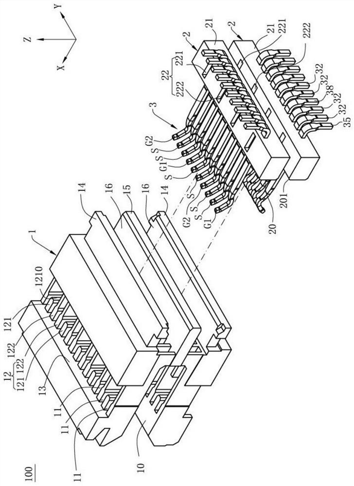
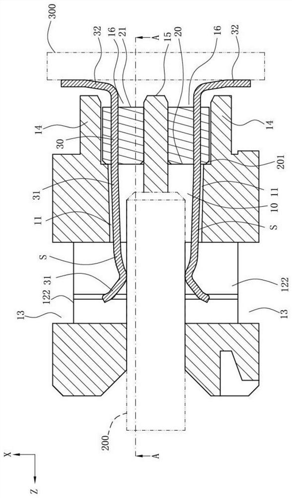
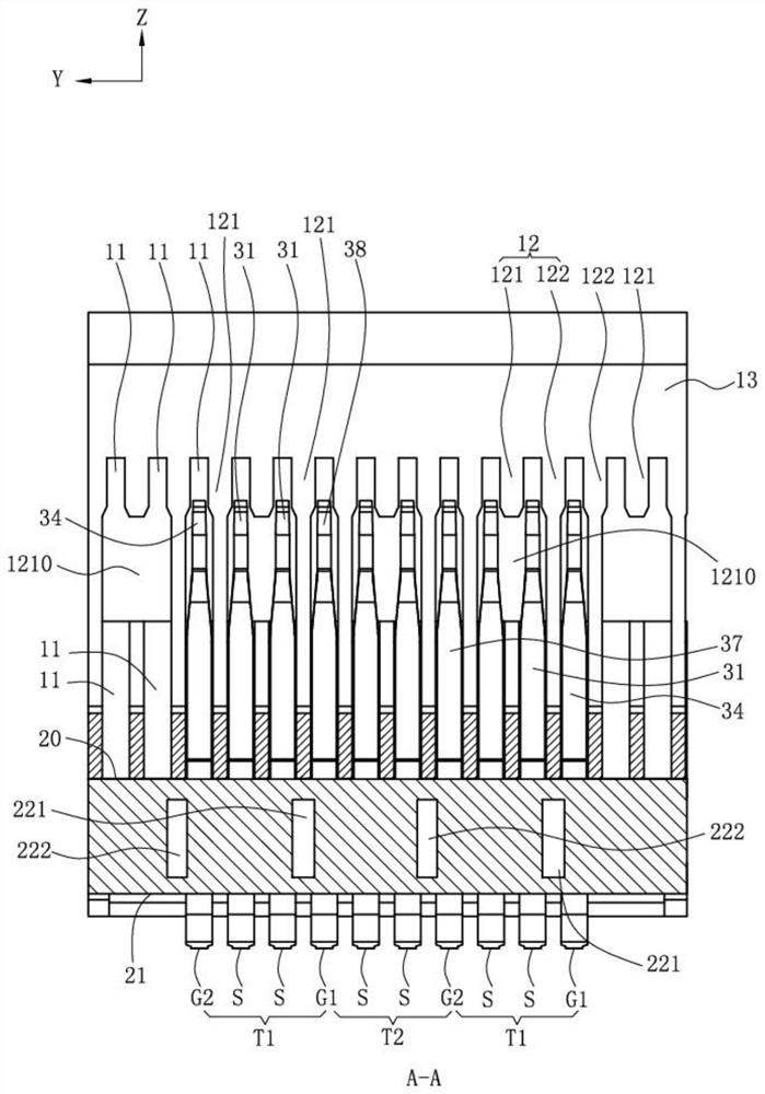
[0053] see figure 1 , figure 2 with image 3 , which is an electrical connector 100 according to a specific embodiment of the present invention. The electrical connector 100 is electrically connected to a first electronic component 200 and a second electronic component 300, and the high-frequency signal of the first electron...


PUM


Abstract

The invention discloses an electric connector. The electric connector includes a plastic block having a butt joint surface and a mounting surface, and a row of terminals having a pair of signal terminals, wherein each signal terminal has an intermediate portion and an extension arm extending forwards from the intermediate portion, the intermediate portion has a contraction portion, width of the contraction portion is smaller than width of a back end of the extension arm, a first ground terminal is arranged at one side of the signal terminal and has a first fixing portion, the first fixing portion and the adjacent intermediate portion are arranged at a first fixed center spacing interval, a first distance is formed between the first fixing portion and the adjacent contraction portion, a second ground terminal is arranged at the other side of the signal terminal, the second ground terminal has a second fixing portion fixed on the plastic block, the second fixing portion and the adjacentintermediate portion are arranged at a second fixed center spacing interval, a first center spacing is equal to a second center spacing, a second distance is formed between the second fixing portion and the adjacent contraction portion, and the second distance is smaller than the first distance.

Description

【Technical field】 [0001] The invention relates to an electrical connector, in particular to a high-frequency connector. 【Background technique】 [0002] An electrical connector, an insulating body, and a row of terminals in the insulating body. A row of terminals is alternately arranged with multiple pairs of differential signal terminals and multiple ground terminals. The ground terminals form a signal ground loop to shield the differential signal terminals. effect. [0003] However, the ground terminal has different geometric shapes at different positions and the surrounding medium is different at different positions, which leads to the inability to maintain zero potential difference between adjacent positions of the ground terminal, and different potentials at different positions , There are also different potentials between multiple ground loops, which makes the ground terminal carry undesired transmission modes. These undesired transmission modes mainly appear as ground...

Claims


Application Information

Patent Timeline
Patent Type & Authority Patents(China)
IPC IPC(8): H01R12/72H01R12/73H01R12/79H01R13/02H01R13/405H01R13/504H01R13/646H01R13/6477H01R13/6474H01R13/6473H01R13/648
CPCH01R12/721H01R12/737H01R12/79H01R13/02H01R13/405H01R13/504H01R13/646H01R13/6473H01R13/6474H01R13/6477H01R13/648
Inventor 隆权
Owner DEYI PRECISION ELECTRONIC IND CO LTD PANYU
Why Eureka
Try Eureka