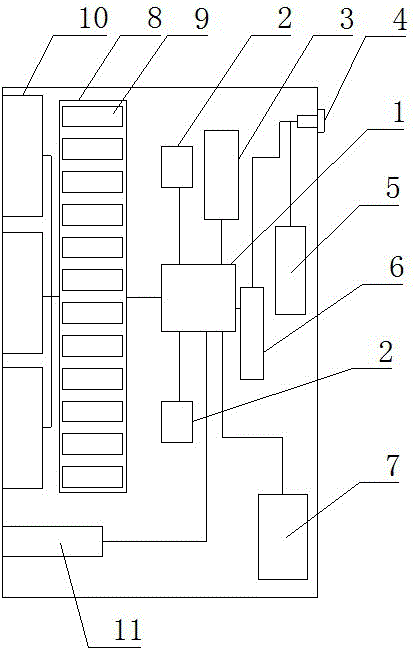
24-channel optical switch circuit
A technology of optical switches and circuits, applied in data exchange networks, electrical components, digital transmission systems, etc., can solve the problems of complex circuit structure, low heat of switches, and large number of components, and achieve stable and high-efficiency work, low failure rate, Efficient work effect
- Summary
- Abstract
- Description
- Claims
- Application Information
AI Technical Summary
Problems solved by technology
Method used
Image
Examples
Embodiment 1
[0014] Such as figure 1 As shown, a 24-way optical switch circuit, which includes a main control chip 1, the upper and lower sides of the main control chip 1 are connected with auxiliary control chips 2, and the main control chip 1 is connected with a crystal oscillator circuit 3, so The power input terminal of the main control chip 1 is connected with a capacitor protection circuit 6, the capacitor protection circuit 6 is connected with a power interface 4, and the output terminal of the power interface 4 is connected with a capacitor circuit 5, and the main control chip 1 is connected with a capacitor circuit 5. The lower right side of the chip 1 is connected with an external protection circuit 7, and the left side of the main control chip 1 is connected with a network port control circuit 8, and the network port control circuit 8 includes network port control chips 9 arranged side by side. The above-mentioned network port control circuit 8 is connected with a network port 1...
Embodiment 2
[0017] Such as figure 1 As shown, a 24-way optical switch circuit, which includes a main control chip 1, the upper and lower sides of the main control chip 1 are connected with auxiliary control chips 2, and the main control chip 1 is connected with a crystal oscillator circuit 3, so The power input terminal of the main control chip 1 is connected with a capacitor protection circuit 6, the capacitor protection circuit 6 is connected with a power interface 4, and the output terminal of the power interface 4 is connected with a capacitor circuit 5, and the main control chip 1 is connected with a capacitor circuit 5. The lower right side of the chip 1 is connected with an external protection circuit 7, and the left side of the main control chip 1 is connected with a network port control circuit 8, and the network port control circuit 8 includes network port control chips 9 arranged side by side. The network port control circuit 8 is connected with a network port 10, the input por...
PUM
 Abstract
Description
Claims
Application Information
 - R&D
- Intellectual Property
- Life Sciences
- Materials
- Tech Scout
- Unparalleled Data Quality
- Higher Quality Content
- 60% Fewer Hallucinations
Browse by: Latest US Patents, China's latest patents, Technical Efficacy Thesaurus, Application Domain, Technology Topic, Popular Technical Reports.
© 2025 PatSnap. All rights reserved.Legal|Privacy policy|Modern Slavery Act Transparency Statement|Sitemap|About US| Contact US: help@patsnap.com

