Heat radiating device

A technology of heat dissipation device and thermal fluid, which is applied in the field of communication, can solve problems such as not found, and achieve the effect of increasing battery life and rapid heat dissipation

Inactive Publication Date: 2017-02-22
ZTE CORP
View PDF0 Cites 6 Cited by
  • Summary
  • Abstract
  • Description
  • Claims
  • Application Information

AI Technical Summary

Problems solved by technology

Most of the existing technologies focus on heat dissipation by adding heat dissipation modules in portable terminal products, and no existing technology has been found to us

Method used


Image

  • Heat radiating device
  • Heat radiating device
  • Heat radiating device

Examples


Example Embodiment

[0039] Example 1

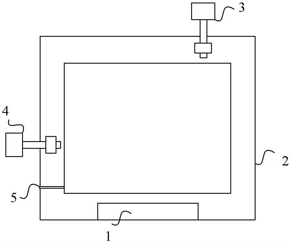
[0040] In this embodiment, the heat conduction module and the generator module are nested together to form the core components of the device, such as figure 2 As shown, it includes: thermal fluid 1, closed copper tube 2, generators 3 and 4, gravity check shrapnel 5.

[0041] The heat conduction liquid storage box of the heat conduction module is made of copper, which is in full contact with the heating area in the portable terminal product, and the contact gap is filled with silver-containing silicone grease to ensure the contact area and heat conduction efficiency.

[0042] When the thermal fluid 1 absorbs the heat emitted by the portable terminal product, the volume expands and flows in the direction indicated by the arrow, pushing the blades of the generator 3 to rotate to generate electric energy. The thermal fluid 1 flows through the generator 3 and continues to flow along the copper tube, using its own gravitational potential energy to push the blade...

Example Embodiment

[0043] Example 2

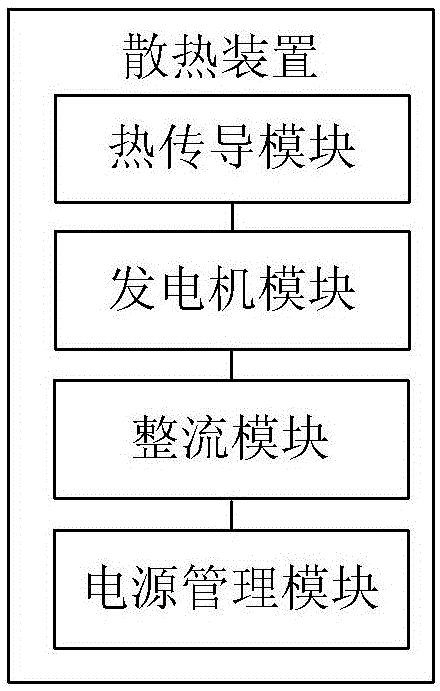
[0044] A heat dissipation device applicable to portable terminal products in this embodiment includes: a heat conduction module, a permanent magnet DC generator, a power management module and a battery module. The heat conduction module and the miniature permanent magnet DC generator are nested together to form the core part of the cooling device of this embodiment, and the electric energy generated by waste heat is used to charge the battery through the power management chip.

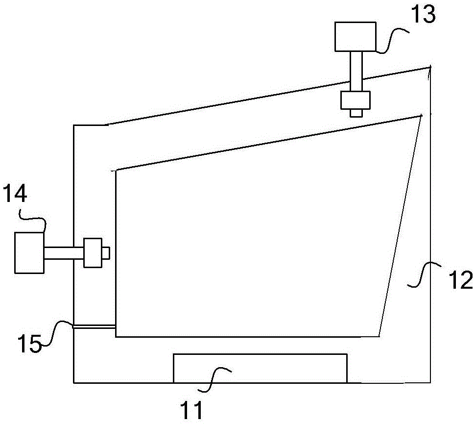
[0045] The module composed of heat conduction module and permanent magnet DC generator nesting is as follows: image 3 shown. Wherein, 11 is the thermal fluid methyl silicone oil, 12 is the closed copper tube, 13 and 14 are the permanent magnet DC generators, and 15 is the gravity check shrapnel. The thermal fluid storage box of the thermal conduction module is made of copper, which is in full contact with the heating area inside the portable terminal product, and the contact gap i...


PUM


Abstract

The invention provides a heat radiating device which comprises the components of a heat conduction module that comprises a closed heat conduction pipe, wherein the heat conduction pipe is internally provided with a heat conduction liquid storage box for storing heat conduction liquid, the heat conduction liquid storage box sufficiently contacts with a heating area in a terminal, the heat conduction pipe is provided with one or a plurality of power generator modules, blades of the engine module are arranged in the heat conduction pipe, the heat conduction liquid flows along a preset path of the heat conduction pipe after heat-absorption and expansion, thereby pushing the blades of the power generator module for generating electric energy, and finally the heat conduction liquid flows back to the heat conduction liquid storage box; the engine module which generates electric energy through pushing of the heat conduction liquid and outputs the electric energy to a power supply management module; and a power supply management module which charges the battery of the terminal by means of the received electric energy. The heat radiating device has advantages of realizing quick heat radiation of a portable terminal product, performing energy recycling on the heat conduction liquid in flowing after heat-absorption and expansion, and storing the recycled electric energy for prolonging duration time of the portable terminal product.

Description

technical field [0001] The invention relates to the communication field, in particular to a heat dissipation device. Background technique [0002] With the continuous improvement of the performance of portable terminal products, the problems of battery life and heat dissipation have become more and more prominent. At present, battery life mainly relies on large-capacity batteries or mobile power sources; the heat dissipation method of portable terminal products is mainly based on the internal structure of a large number of graphite heat dissipation stickers, and the single-point heat generated by the main chip is evenly transmitted to the metal steel plate of the portable terminal product. Natural heat dissipation, the heat generated is not used effectively. [0003] A thermoelectric semiconductor can be used in a thermal power generation device alone. The thermoelectric semiconductor has a hot surface and a cold surface. The larger the temperature difference between the tw...

Claims


Application Information

Patent Timeline
IPC IPC(8): H05K7/20
CPCH05K7/20
Inventor 杜泳锋李军
Owner ZTE CORP
Why Eureka
Try Eureka