Milking device

A technology of cleaning device and monitoring device, applied in milking device, milk container, cleaning method using liquid, etc., can solve the problems of lack of control, insufficient control of cleaning effect, etc.

Active Publication Date: 2017-02-22
LELY PATENT
View PDF5 Cites 10 Cited by
  • Summary
  • Abstract
  • Description
  • Claims
  • Application Information

AI Technical Summary

Problems solved by technology

[0004] A problem with known milking units is that the cleaning action cannot be adequately controlled by cleaning liquids such as hot water
This lack of control is undesirable because milking systems must be cleaned and sanitized in order to provide high quality milk for consumption

Method used


Image

  • Milking device
  • Milking device
  • Milking device

Examples


Embodiment Construction

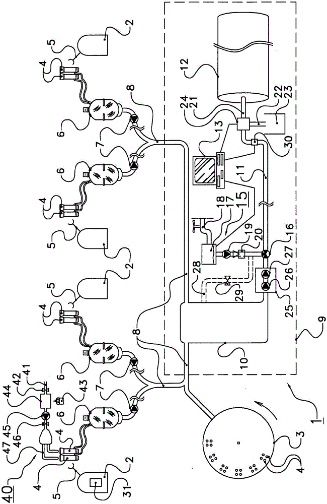
[0034] figure 1 A height schematic view of a milking system 1 according to the invention is shown. Here, the milking system 1 also includes a carousel 3 plus four milking robot devices 2 . Each milking robot device 2 has a teat cup 4 and a clamp arm 5 to allow the teat cup to be attached to the teat of a dairy farm animal. In addition, there are in each case: a milking glass 6 for collecting milk from the milking operation; and a milk pump 7 for pumping milk through a milk duct 8 to a milk storage system 9 , The milk storage system 9 comprises a temporary milk storage container 10 connected to a milk storage tank 12 via a main milk conduit 11 .

[0035] Reference numeral 13 denotes a control unit, reference numeral 15 denotes a pressurized liquid supply source connected to the main milk line 11 through a second selection means 16, a boiler 17, a water line supply source 18, a pump 19 and flow meter 20 .

[0036] Furthermore, reference numeral 21 designates a first discharg...


PUM


Abstract

Milking system comprising: several milking devices (4), each having a milk-carrying part, a temporary milk storage vessel (10), a milk pipe system (8), a milk storage tank (12), and a main milk pipe (11), which connects the temporary milk storage vessel to the milk storage tank, wherein the milking system furthermore comprises a first cleaning device (40) having at least one first cleaning liquid supply and at least a pump, which cleaning device is configured to clean at least the milk-carrying part of at least one milking device and a part of the milk pipe system which connects the milk-carrying part to the temporary milk storage vessel, by transferring cleaning liquid from the cleaning liquid supply through at least the milk-carrying part of the at least one milking device and through said part of the milk pipe system to the temporary milk storage vessel by pumping, wherein the temporary milk storage vessel comprises a main pump for transferring liquid from the temporary milk storage vessel through the main milk pipe in the direction of the milk storage tank, wherein the milking system furthermore comprises a second, additional cleaning device (15) with at least one second, additional cleaning liquid supply,which second cleaning device is configured to supply additional cleaning liquid from the second cleaning liquid supply in a direction of flow from the temporary milk storage vessel towards the main milk pipe, wherein the second cleaning liquid supply is situated downstream of at least each of the milking devices, viewed in said direction of flow.

Description

technical field [0001] The present invention relates to a milking system for use in a dairy farm, wherein the milking system comprises a plurality of milking units, each milking unit having a milk transfer member, a temporary milk storage container such that the temporary milk storage container is connected to each milking A milk piping system to which the milk unit is connected, a milk storage tank and a main milk line connecting the temporary milk storage container to the milk storage tank. Background technique [0002] Such milking systems are known per se, especially for large farms with multiple milking systems. In this case, the milk from the milking operation is first collected in an (optional) milking glass near the milking unit itself, and then passed to a temporary milk storage container, which is a buffer container where the milk From this temporary milk storage container pumps are sent to the final milk storage tank. Especially for large farms such a buffer con...

Claims


Application Information

Patent Timeline
Patent Type & Authority Applications(China)
IPC IPC(8): A01J5/007A01J5/04A01J7/02A01J9/00
CPCA01J5/007A01J5/044A01J7/022A01J9/00A01J5/00B08B3/10B08B9/0325
Inventor R·A·范蒂尔伯格D·戴克舒恩M·J·德胡卢
Owner LELY PATENT
Why Eureka
Try Eureka