Electronic device cooling system

a technology for electronic devices and cooling systems, applied in the direction of electrical apparatus casings/cabinets/drawers, domestic cooling apparatus, heating types, etc., can solve the problems of high electrical power consumption, double hit, power consumption,

Active Publication Date: 2012-07-17
GOOGLE LLC
View PDF67 Cites 93 Cited by
  • Summary
  • Abstract
  • Description
  • Claims
  • Application Information

AI Technical Summary

Benefits of technology

[0016]In another embodiment, a modular system for providing cooling water to a building housing a group of electronic devices includes a module and a water storage. The module includes a housing, wherein the housing is no more than 13.5 feet wide and is no longer than 97 feet, a water-to-water heat exchanger within the housing, a chiller within the housing and a controller within the housing, wherein the controller regulates a flow of water from the water-to-water heat exchanger and the chiller to outside of the housing. The water storage tank has a capacity of at least 10,000 gallons and is fluidly coupled to at least one of the chiller and the water-to-water heat exchanger.

Problems solved by technology

Many forget that this speed often comes with a cost—higher electrical power consumption.
Power consumption also, in effect, creates a double hit.
Thus, the cost of removing all of the heat can also be a major cost of operating large data centers.
That cost typically involves the use of even more energy, in the form of electricity and natural gas, to operate chillers, condensers, pumps, fans, cooling towers, and other related components.
Heat removal can also be important because, although microprocessors may not be as sensitive to heat as are people, increases in heat generally can cause great increases in microprocessor errors and failures.

Method used


Image

  • Electronic device cooling system
  • Electronic device cooling system
  • Electronic device cooling system

Examples


Embodiment Construction

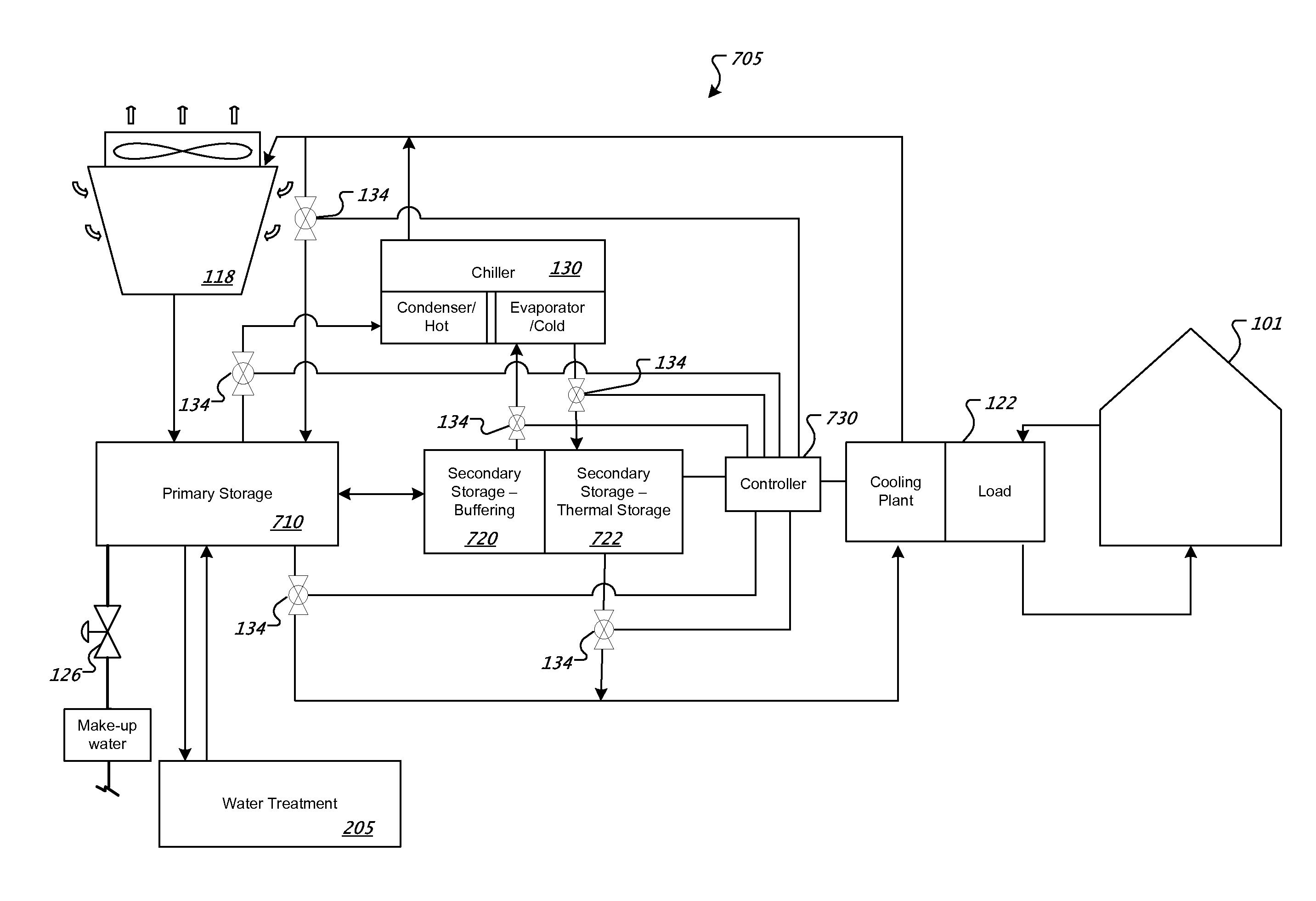
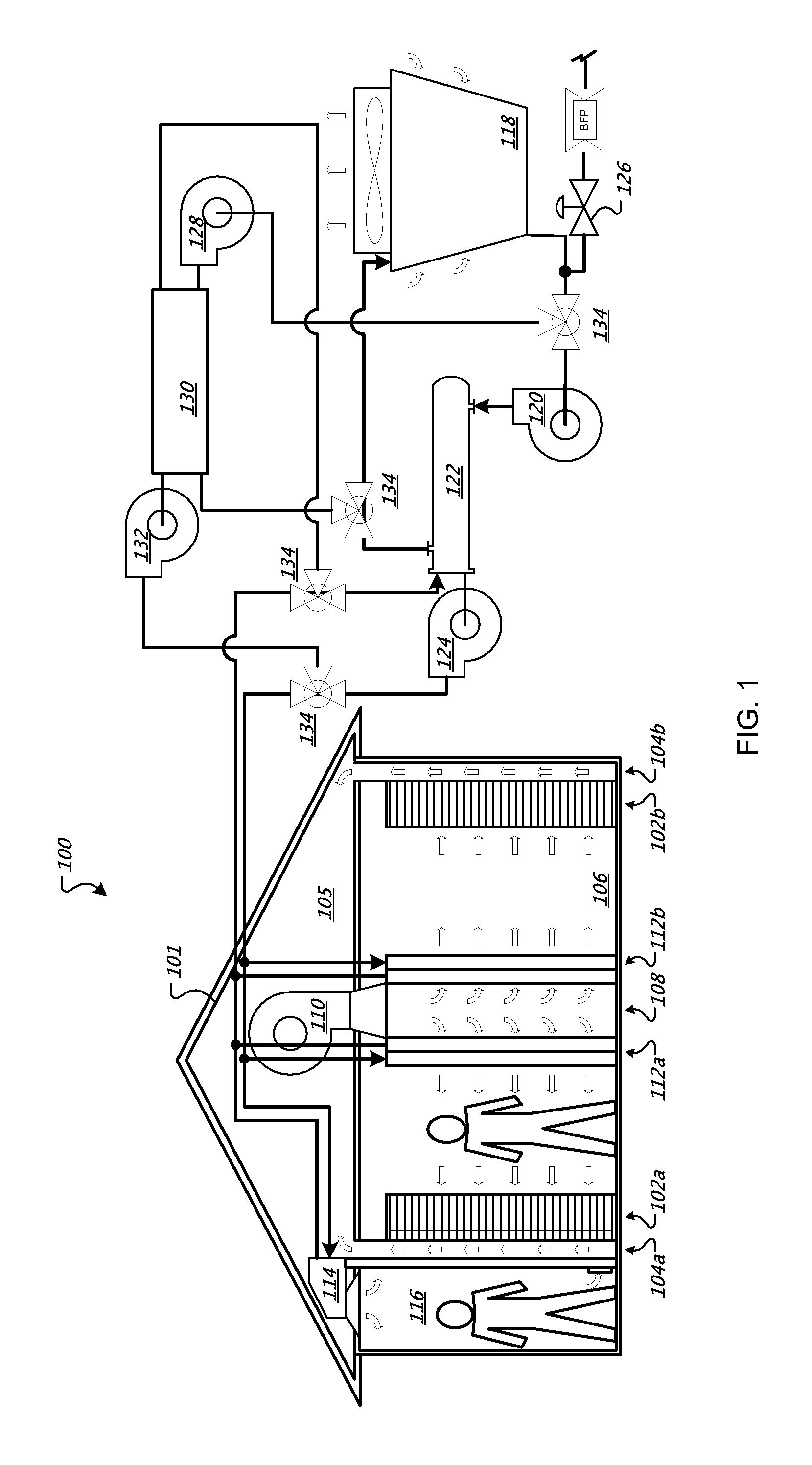
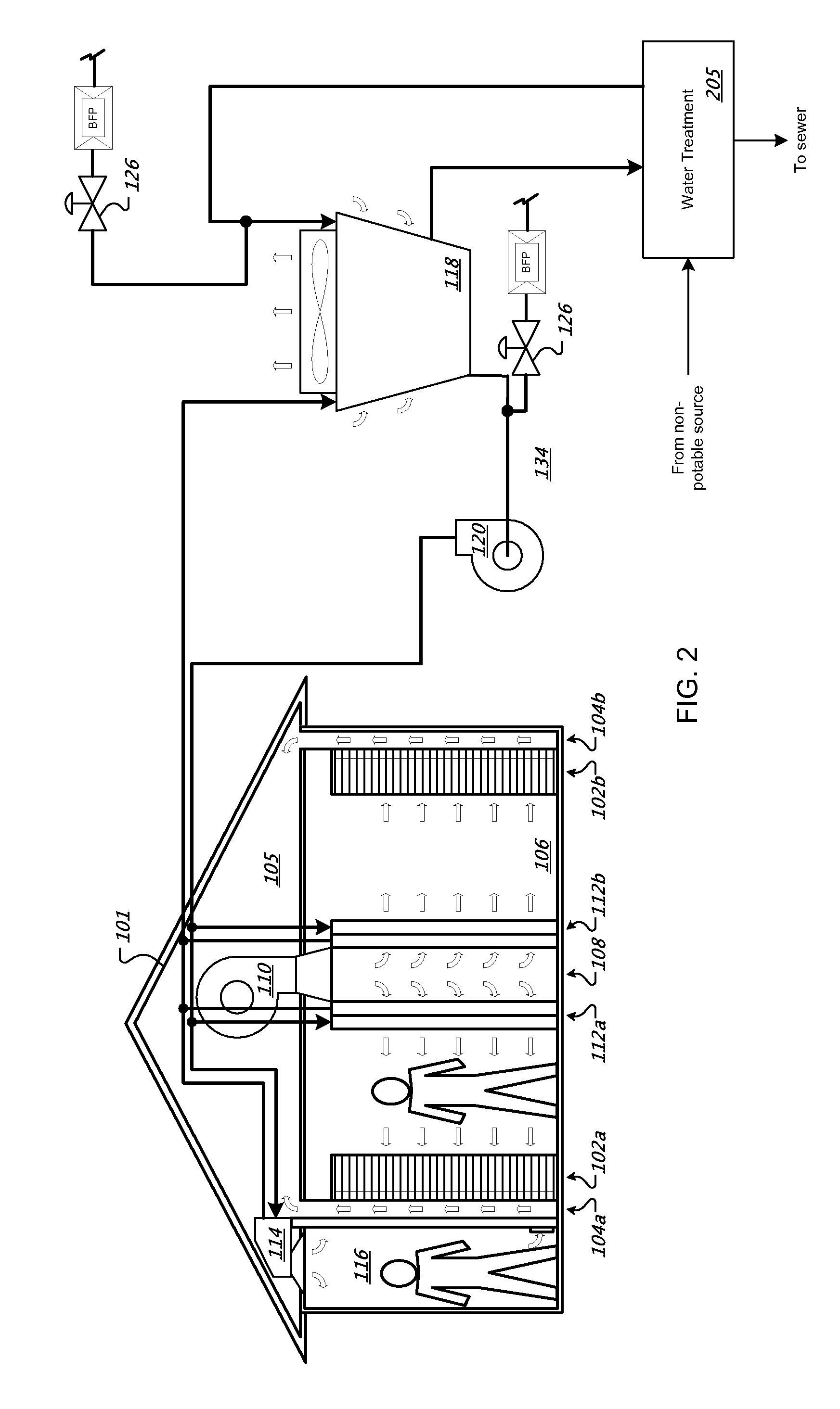
[0031]FIG. 1 is a schematic diagram showing a system 100 for cooling a computer data center 101. The system 100 generally includes an air handling unit (including e.g., fan 110 and cooling coils 112a, 112b) in the data center 101 for transferring heat from the data center's air to cooling water, a heat exchanger 122 for removing heat from the cooling water and passing it to cooling tower water, and a cooling tower 118 to pass the accumulated heat to the ambient air through evaporation and cooling of the cooling tower water. In general operation, the system 100 may be run from the cooling tower / heat exchanger / cooling coil system, though a powered refrigeration system such as a chiller may be provided for peak loads, such as when the outdoor ambient dew point is very high and the cooling tower cannot provide sufficient cooling alone. As explained below, control parameters for the system may also be set so as to avoid most or any need for the use of chillers or other such items.

[0032]T...


PUM


Abstract

Cooling systems for providing cooled air to electronic devices are described. The systems can include large storage tanks or waste treatment systems to improve the efficiency of the plant and reduce impact on the environment.

Description

CROSS-REFERENCE TO RELATED APPLICATIONS[0001]This application is a continuation application and claims the benefit of priority under 35 U.S.C. Section 120 of U.S. application Ser. No. 12 / 060,222, filed on Mar. 31, 2008, which claims priority to U.S. Provisional Application Ser. No. 61 / 016,419, filed on Dec. 21, 2007. The disclosure of each prior application is considered part of and is incorporated by reference in the disclosure of this application.TECHNICAL FIELD[0002]This document relates to systems and methods for providing cooling for areas containing electronic equipment, such as computer server rooms and server racks in computer data centers.BACKGROUND[0003]Computer users often focus on the speed of computer microprocessors (e.g., megahertz and gigahertz). Many forget that this speed often comes with a cost—higher electrical power consumption. For one or two home PCs, this extra power may be negligible when compared to the cost of running the many other electrical appliances i...

Claims


Application Information

Patent Timeline
Patent Type & Authority Patents(United States)
IPC IPC(8): H05K7/20F28D15/00F28F7/00F25D23/12H05K5/00F24S10/30F24S23/70
CPCF24F5/0035H05K7/20836F28B9/06F28D15/00F28C2001/006Y02B30/545F24S10/30F24S23/70Y02B10/20Y02B30/54Y02E10/44H05K7/20381
Inventor CARLSON, ANDREW B.HAMBURGEN, WILLIAM
Owner GOOGLE LLC
Why Eureka
Try Eureka