Liquid and compressed natural gas dispensing system

a liquid and compressed natural gas technology, applied in the direction of container filling under pressure, container discharging methods, packaged goods types, etc., can solve the problems of inefficient liquid filling of multiple tanks, insufficient cooling and pressurizing, and insufficient cooling of cascades, etc., to achieve the effect of reducing the time of cooling

Inactive Publication Date: 2005-01-27
CHART INC
View PDF12 Cites 92 Cited by
  • Summary
  • Abstract
  • Description
  • Claims
  • Application Information

AI Technical Summary

Benefits of technology

[0018] The system may be reconfigured so that a vaporizer alternatively receives LNG from the pump and vaporizes it to create CNG. The vaporizer may direct the CNG to the LNG in the storage tank via a dip tube to saturate it at the pressure required by the vehicle to which it is dispensed. CNG from the vaporizer may alternatively be directed to a pressurizing cylinder so as to recharge it. When dispensing of LNG is desired, the head space of the storage tank is placed in communication with the pressurizing cylinder so that the LNG may be rapidly dispensed.
[0020] Operation of the system may be automated by a controller that communicates with the pump, system valves and pressure, temperature and liquid level sensors or gages. In addition, the system pump may be submerged in LNG in the bulk tank or a sump to eliminate cool-down time.

Problems solved by technology

While cascade filling works well in dispensing CNG, filling multiple tanks with liquid and then conditioning and pressurizing them is inefficient.
As a result, cascade filling is not optimal for the rapid dispensing of LNG.
In addition, both systems, as with many prior art systems, require more than one heat exchanger to operate.
This adds to system complexity and cost.
This is a disadvantage as compressors introduce additional complexity, expense and maintenance requirements.
In addition, each system also requires two heat exchangers which, as described above, also adds to system complexity and cost.
Because of the different storage requirements for LNG and conventional fuels, it is impractical and economically unfeasible to modify existing gasoline distribution facilities for LNG.
An issue exists, however, as to how to create a method to fill the storage tank in a confined, height limited space.
Such an environment does not provide enough height to gravity fill the storage tank.

Method used


Image

  • Liquid and compressed natural gas dispensing system
  • Liquid and compressed natural gas dispensing system
  • Liquid and compressed natural gas dispensing system

Examples


Embodiment Construction

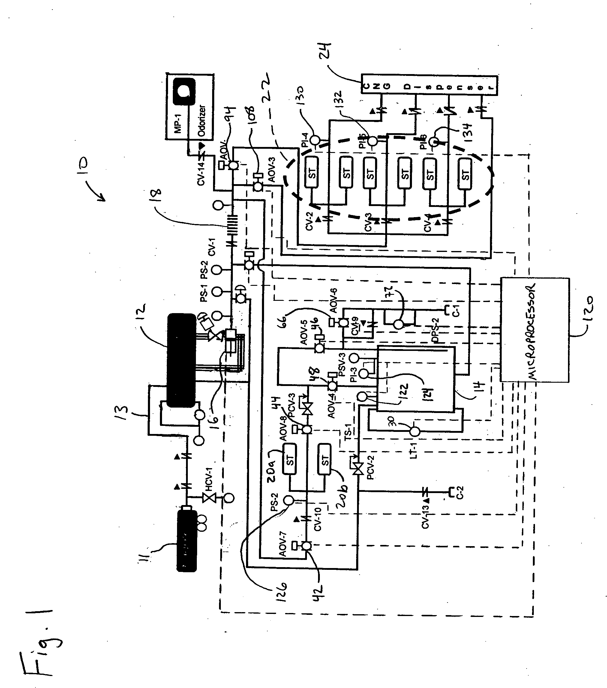
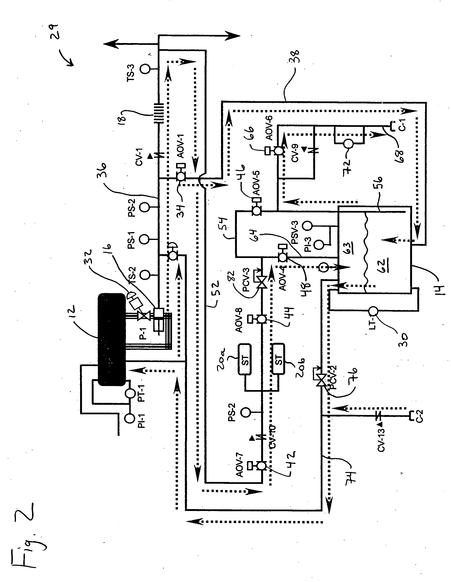
[0027] An embodiment of the system of the present invention is indicated in general at 10 in FIG. 1. The system 10 is self-contained and dispenses liquid natural gas (LNG) and compressed natural gas (CNG) from a horizontal cryogenic bulk tank, indicated at 12, at sites where limited height requirements are an issue. The system, including the bulk tank 12, may be housed, for example, within a 40 foot ISO container and thus may be rapidly installed at a site either temporarily or permanently. The system, as explained below, may also be easily automated.

[0028] While the system of the present invention is described below in terms of dispensing CNG and LNG to vehicles, it could alternatively be used dispense other types of cryogenic fluids to other types of use devices.

[0029] The bulk tank 12 of the system 10 preferably has a capacity of approximately 5000 gallons for storing LNG. It may be refilled by a transport 11 carrying a supply of LNG through line 13. The system 10 also includes...


PUM

PropertyMeasurementUnit
volumeaaaaaaaaaa
pressureaaaaaaaaaa
pressureaaaaaaaaaa

Abstract

A system dispenses both liquid natural gas (LNG) and compressed natural gas (CNG). A bulk tank contains a supply of LNG which is pumped to a smaller storage tank. After the storage tank is refilled, LNG from the bulk tank is pumped to a vaporizer so that CNG is produced. The CNG may be routed to the LNG in the storage tank to condition it. It is also used to recharge a pressurizing cylinder that is placed in communication with the head space of the storage tank when it is desired to rapidly dispense LNG to a vehicle. A bank of cascaded storage cylinders alternatively may receive CNG from the vaporizer for later dispensing through the system CNG dispenser. The CNG from the vaporizer may also be dispensed directly via the system CNG dispenser.

Description

PRIORITY CLAIM [0001] This application claims priority from U.S. Provisional Patent Application Ser. No. 60 / 407,042, filed Aug. 30, 2002, and currently pending.BACKGROUND OF THE INVENTION [0002] The present invention relates generally to systems for dispensing cryogenic fluids and, more particularly, to a self-contained system for dispensing liquid natural gas and compressed natural gas. [0003] Economic and environmental concerns have resulted in widespread efforts to develop fuel substitutes for gasoline and diesel fuel. Natural gas, whose main component is methane, presents a viable alternative to gasoline and diesel fuel because it is relatively inexpensive, burns cleanly and produces emissions which are much less harmful to the environment. Both compressed natural gas (CNG) and liquid natural gas (LNG) have found use as alternative fuels in vehicles. Accordingly, it is desirable to have a system that can dispense both CNG and LNG. [0004] LNG typically must be conditioned prior t...

Claims


Application Information

Patent Timeline
Patent Type & Authority Applications(United States)
IPC IPC(8): F17C5/00F17C5/02F17C5/06F17C7/02F17C7/04F17C9/00F17C9/02F17C13/02
CPCF17C5/007F17C2270/0168F17C5/06F17C7/02F17C9/00F17C9/02F17C13/025F17C13/026F17C2205/0332F17C2221/033F17C2223/0161F17C2223/033F17C2223/046F17C2225/0123F17C2225/0161F17C2225/033F17C2225/035F17C2225/036F17C2225/043F17C2225/046F17C2225/047F17C2227/0107F17C2227/0142F17C2227/0178F17C2227/0302F17C2227/0393F17C2227/043F17C2250/01F17C2250/032F17C2250/0408F17C2250/043F17C2250/0439F17C2250/0443F17C2250/0452F17C2260/025F17C2265/022F17C2270/0139F17C5/02
Inventor EMMER, CLAUS D.GAMBLE, JESSEZELASKO, CRAIGDRUBE, THOMAS K.
Owner CHART INC
Why Eureka
Try Eureka