Apparatus for sensing and controlling gas supply amount, and method for sensing and controlling gas supply amount thereby

A technology for adjusting devices and supply, applied in measuring devices, applications, horticultural methods, etc., can solve problems such as large operating problems, and there is no means of publicly modifying the appropriate supply, so as to achieve the effect of accurate identification

Active Publication Date: 2017-02-22
ECINU
View PDF8 Cites 0 Cited by
  • Summary
  • Abstract
  • Description
  • Claims
  • Application Information

AI Technical Summary

Problems solved by technology

[0007] However, all of the conventional technical ideas including the above-mentioned authorized patents do not provide a means of grasping the supply status of CO2 supply in real time, so there are great operational problems
[0008] That is, when the supply of carbon dioxide changes suddenly due to the internal conditions of the aquarium or external factors, this situation cannot be grasped immediately, and not only that, but also the means for modifying the appropriate supply in various situations is not disclosed. Therefore, a more effective method is required. related system

Method used


Image

  • Apparatus for sensing and controlling gas supply amount, and method for sensing and controlling gas supply amount thereby
  • Apparatus for sensing and controlling gas supply amount, and method for sensing and controlling gas supply amount thereby
  • Apparatus for sensing and controlling gas supply amount, and method for sensing and controlling gas supply amount thereby

Examples


Embodiment Construction

[0028] Hereinafter, referring to the accompanying drawings, the structure, function and effect of the present invention will be described together.

[0029] The advantages and features of the present invention, as well as the method for realizing the advantages and features, can be clarified with reference to the embodiments described in detail in the accompanying drawings. However, the present invention is not limited to the embodiments disclosed below, and the present invention can be embodied in various forms. This embodiment is only because the disclosure of the present invention is relatively complete, and it is for those who have common knowledge in the technical field to which the present invention belongs. It is provided that the scope of the invention is fully informed, and the present invention is defined by the scope of claims. In addition, the same reference numeral refers to the same constituent element throughout the specification.

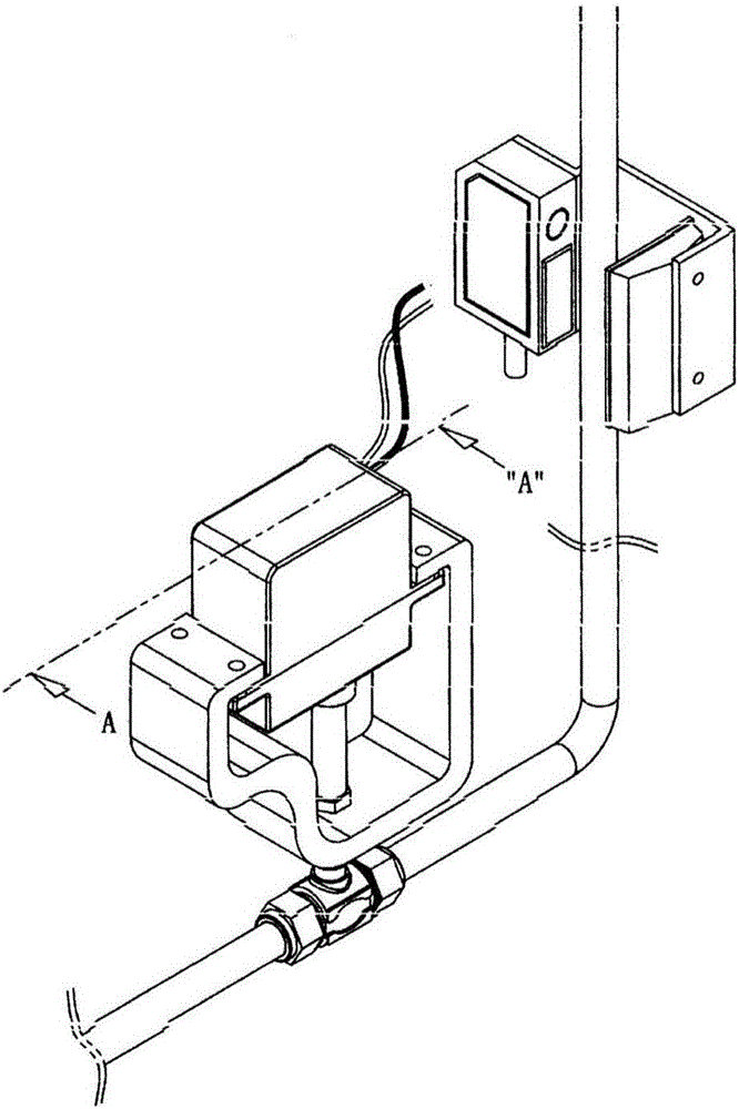
[0030] figure 1 It is a per...


PUM


Abstract

The present invention relates to an apparatus for sensing and controlling a gas supply amount, and a method for sensing and controlling a gas supply amount thereby, the apparatus being configured so as to be capable of continuously maintaining the originally preset supply amount while allowing the gas supply amount to be sensed in real time by a light sensor on the basis of the number of bubbles generated at an arbitrarily set time difference when target gas flows in a tube, thereby being capable of identifying more accurately the supply amount or faulty supply state, wherein a series of automated devices control the pressure of the tube in real time so as to precisely realize a target supply amount according to gas supply information obtained from the light sensor, thereby actively preventing malfunction. The apparatus comprises: a tube (1) which allows target gas to flow from the bottom to the top; a sensing unit (10), engaged with the external surface of the tube, for sensing the number of bubbles of the target gas, which sequentially moves for a predetermined period of time in the inner space of the tube, in real time, through application of the light sensor on the basis of signal information of a light emitting diode and a transistor positioned to correspond to each other; a control unit for receiving bubble information from the sensing unit and determining whether the bubble information matches the target gas supply amount in comparison to a preset time; and a pressure adjustment unit (20), operated by signals obtained from the control unit, for determining whether to block the inner space of the tube in a manner that the pressure adjustment unit (20) rotates at an angle proportional to the number of pulses provided through a motor, thereby varying the number of bubbles during a certain period of time to match the target gas supply amount.

Description

technical field [0001] The present invention relates to a gas supply amount induction adjustment device and an induction adjustment method using the device. The gas supply amount induction adjustment device has the following structure: a series of automatic equipment devices can control the pressure of the pipe in real time, effectively prevent operation errors, and The initially set supply amount is continuously executed, and the device senses the supply amount of the gas in real time from the optical sensor based on the number of bubbles generated with an arbitrarily set time difference when the target gas flows in the pipe, so that it can be more accurately identified Whether the supply amount and the supply state are correct or not, and realize the accurate target supply amount based on the gas supply information acquired from the optical sensor. Background technique [0002] At present, there are more and more families or enterprises cultivating ornamental fish and aqua...

Claims


Application Information

Patent Timeline
Patent Type & Authority Applications(China)
IPC IPC(8): A01K63/04G01F1/7086
CPCA01K63/042G01F1/7086G01N21/85G01P13/0086G01F1/704G01F1/74G01F15/002A01G7/02G01F1/00A01K63/006G01N21/59
Inventor 李信雨
Owner ECINU
Why Eureka
Try Eureka