Composite member and cutting tool

A technology of composite parts and joining parts, which is applied in the direction of manufacturing tools, boring machine/drilling machine parts, drilling tool accessories, etc., to achieve excellent cutting performance and improved joint strength

Active Publication Date: 2017-02-22
MITSUBISHI MATERIALS CORP
View PDF11 Cites 9 Cited by
  • Summary
  • Abstract
  • Description
  • Claims
  • Application Information

AI Technical Summary

Problems solved by technology

[0018] Therefore, in order to solve the problems of the existing composite parts and cutting tools made of the composite parts, the present inventors made a composite part made of cBN sintered body and WC-based cemented carbide (for example, after ultrahigh-pressure high-temperature sintering When the cBN sintered body is sintered and the WC-based cemented carbide substrate is bonded at the same time, the composite sintered body), or the cutting edge part composed of a single component of the cBN sintered body and the WC-based cemented carbide tool substrate are bonded via the bonding member. As a result of in-depth research on countermeasures to improve the joint strength of the joint, the following insights were obtained

Method used


Image

  • Composite member and cutting tool
  • Composite member and cutting tool
  • Composite member and cutting tool

Examples


Embodiment

[0081] As raw material powders, WC powder, VC powder, TaC powder, NbC powder, Cr, all having an average particle diameter of 0.5 to 1 μm are prepared 3 C 2 Powder and Co powder, these raw material powders were blended into the blending composition shown in Table 1, and they were wet-mixed by a ball mill for 24 hours. After drying, they were press-formed into compacts at a pressure of 100 MPa, and the compacts were placed in a vacuum of 6 Pa Sintering was performed under the conditions of a temperature of 1400° C. and a holding time of 1 hour to form four types of WC-based cemented carbide sintered bodies (hereinafter referred to as "cemented carbides") A-1 to A-4 shown in Table 1.

[0082] [Table 1]

[0083]

[0084] Next, as the raw material powder of the cBN sintered body, cBN powder, TiN powder, TiCN powder, TiB each having an average particle diameter in the range of 0.5 to 4 μm were prepared. 2 Powder, TiC powder, AlN powder, Al 2 O 3 Powders. These raw material powders are ble...


PUM

PropertyMeasurementUnit
thicknessaaaaaaaaaa
thicknessaaaaaaaaaa
thicknessaaaaaaaaaa

Abstract

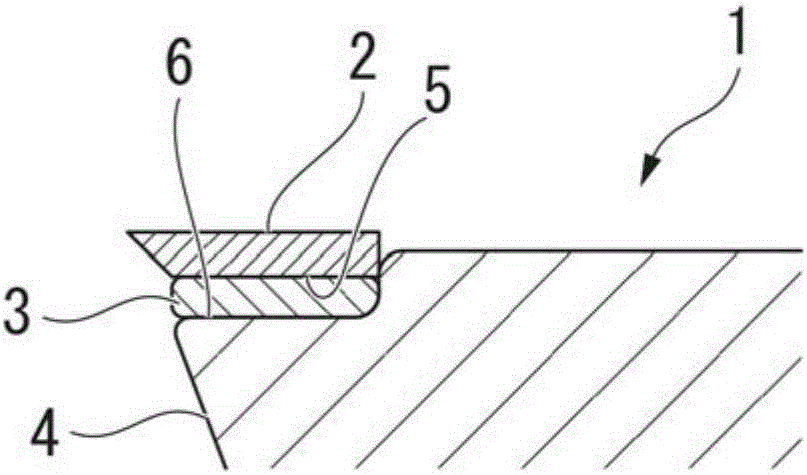
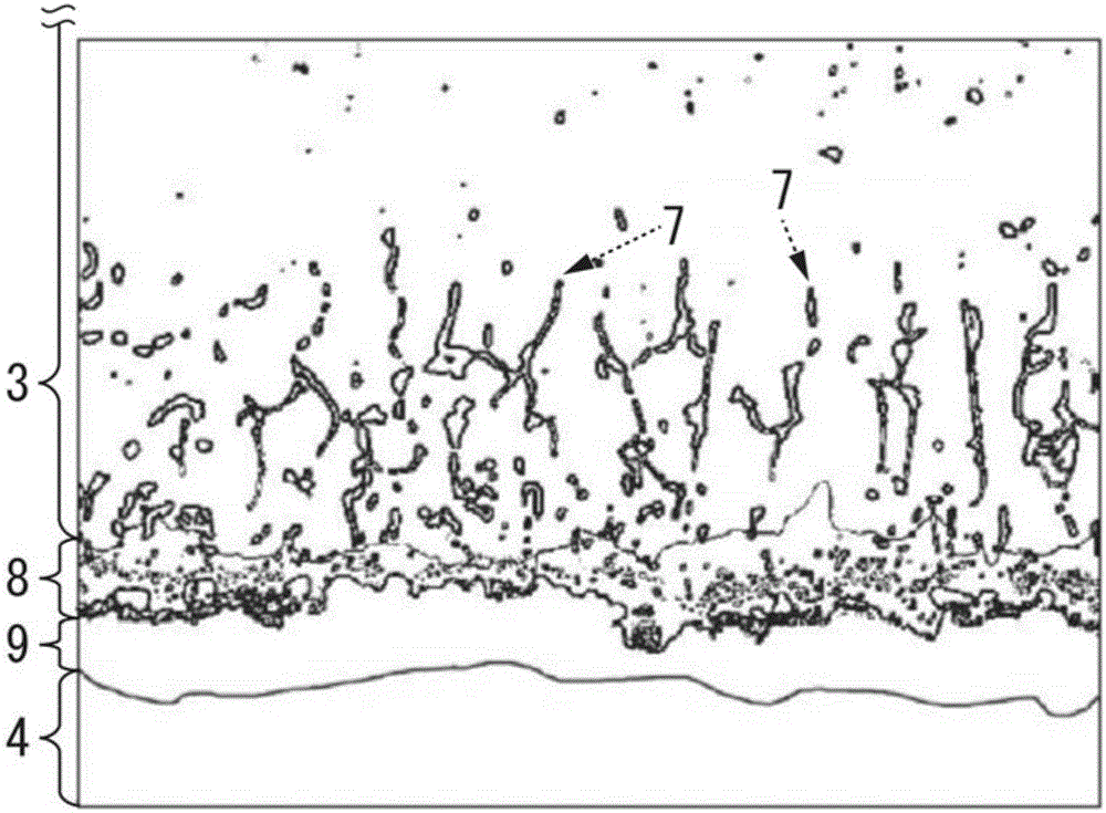
Provided is a composite member (1) comprising: a cutting edge part (2) formed of a cubic boron nitride sintered compact or WC group cemented carbide; a tool base body (4) formed of WC group cemented carbide; and a bonding member (3) which is disposed between the cutting edge part and the tool base body and bonds the cutting edge part to the tool base body. A TiC-based layer (9), which has an average layer thickness of 0.5-3 [mu]m and contains 50% by area or more of TiC, is formed at the interface between the cemented carbide and the bonding member. Also, a TiNi-concentrated layer (8), which has an average layer thickness of 0.3-3 [mu]m and contains Ti and Ni each in an amount of 30% by atom or more, is formed adjacent to the TiC-based layer in the bonding member side. Further, an intermittent mesh structure (7), which contains Ti, Ni and C each in an amount of 10% by atom or more and has an average width of 10-200 nm, and in which lines connecting the major axes of individual crystal grains containing Ti, Ni and C each in an amount of 10% by atom or more cross three or more, on average, other crystal grains containing Ti, Ni and C each in an amount of 10% by atom or more, is formed adjacent to the TiC-based layer in the bonding member side.

Description

Technical field [0001] The invention of the present application relates to a composite part and a cutting tool with excellent joint strength of the joint, and more particularly to a composite part in which a sintered body of cubic boron nitride (hereinafter referred to as cBN) and a WC-based cemented carbide are joined, and A cutting tool composed of this composite part. [0002] This application claims priority based on Patent Application No. 2014-059529 filed in Japan on March 24, 2014, and uses the content here. Background technique [0003] In recent years, cutting tools such as inserts or end mills using cBN sintered bodies for cutting edges have been provided as tools for processing metal molds used in the manufacture of housings for mobile phones and smartphones. The cBN sintered body exhibits high productivity and long life, and has a hardness second only to diamond. [0004] However, the cBN sintered body itself is difficult to process and expensive, and the shape of the s...

Claims


Application Information

Patent Timeline
Patent Type & Authority Applications(China)
IPC IPC(8): B23B27/18B23B27/14B23B51/00B23C5/16
Inventor 五十岚诚
Owner MITSUBISHI MATERIALS CORP
Why Eureka
Try Eureka