Method for calibrating a robot and a robot system

A robot system and robot technology, applied in the field of calibration robots, can solve problems such as difficult optimization problems and limited final accuracy of parameters

Active Publication Date: 2017-02-22
ABB (SCHWEIZ) AG
View PDF6 Cites 17 Cited by
  • Summary
  • Abstract
  • Description
  • Claims
  • Application Information

AI Technical Summary

Problems solved by technology

[0008] The disadvantage of this simultaneous optimization of robot and camera parameters is that several additional camera parameters must be i

Method used


Image

  • Method for calibrating a robot and a robot system
  • Method for calibrating a robot and a robot system
  • Method for calibrating a robot and a robot system

Examples


Embodiment Construction

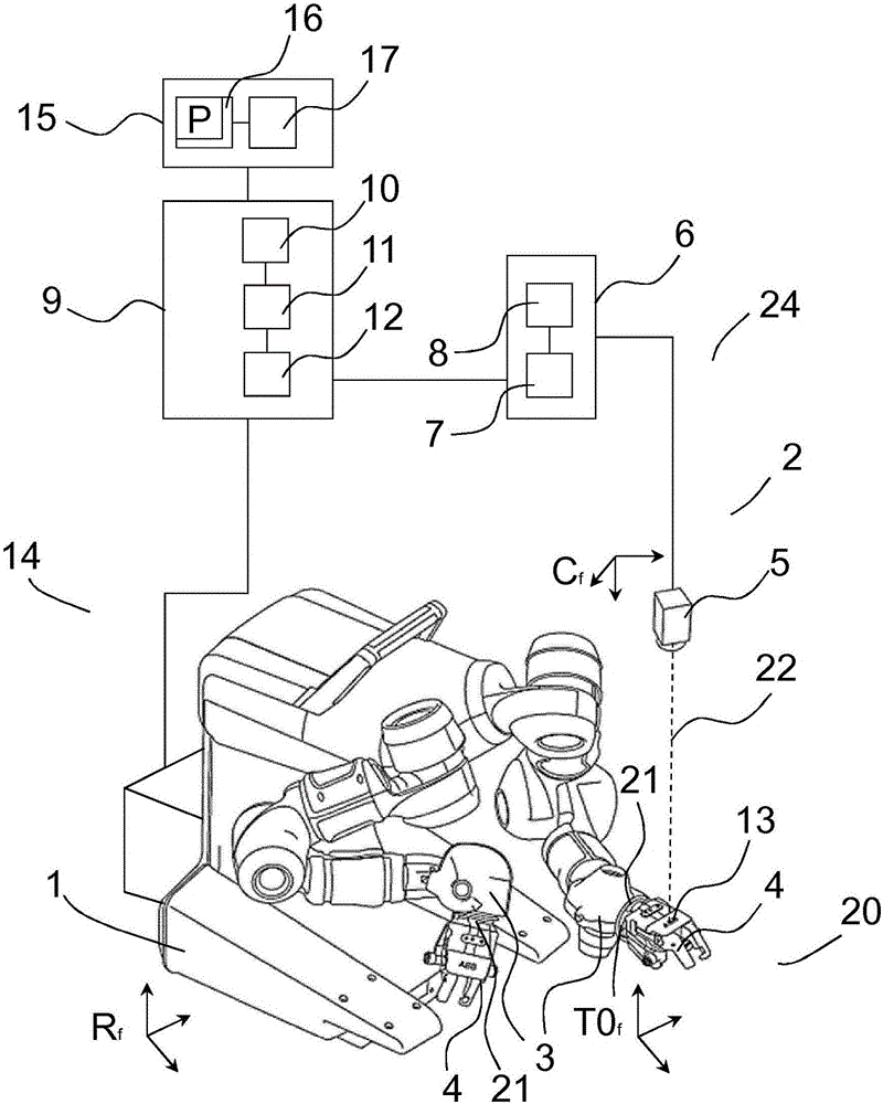
[0041] figure 1 An example of a robotic system 14 is illustrated. The robot system 14 includes defining the robot coordinate system R f The robot 1 and define the camera coordinate system C f Object Recognition Unit 2. Robot 1 is a redundant robot and has seven degrees of freedom. figure 1 The robot 1 shown in is a dual-arm robot with two robot arms 3, but the invention can be used with all types of robots. Specifically, the present invention is also applicable to articulated robots having six degrees of freedom.

[0042] figure 1 Each robot arm 3 in has a plurality of links connected in series. The movement of each of these linkages may be a translational movement or a rotation about an axis or a combination. These two changes in movement give each link a mechanical degree of freedom around or along what will hereinafter be referred to as a joint. The joints may be actuated by servo-controlled motors, controlled via feedback from the measured motion of the motors. In t...


PUM


Abstract

A method for calibrating a robot, wherein the robot comprises a movable part with a calibration marker. The method comprising: positioning the calibration marker in a plurality of positions along an optical line of a camera unit; imaging the calibration marker at the plurality of positions along the optical line to establish line positions P 1 ... P N of the calibration marker along the optical line within a tolerance k, while monitoring joint values j 1 ... j M of the robot; establishing an error function based on resulting calculated robot positions P' 1 ... P' N for the calibration marker for joint values j 1 ... j M at each line position P 1 ... P N for the calibration marker; identifying a set of robot kinematic parameters by solving an optimization problem based on the error function; and updating a kinematic model of the robot by means of the identified set of robot kinematic parameters. It is also referred to a robot system, a robot controller, a robot unit, use of a robot unit, a computer program P and a computer readable storage medium.

Description

technical field [0001] The present invention relates to techniques for calibrating robots, and in particular to methods and robotic systems for calibrating robots. The invention also relates to a robot controller, a robot cell, the use of a robot cell, a program for calibrating a robot, and a computer readable medium. Background technique [0002] To calculate the position of the robot end effector based on the robot joint values, a kinematic model of the robot can be used. For high-precision positioning of the robot, the kinematic parameters of the robot must be precisely identified. The process of performing some motion with a robot, measuring the result, and adjusting the calculated result to the measured result by adjusting the kinematic parameters is called robot calibration. [0003] Most commonly, external measurement systems are used for calibration. Typically, the measurement system is a high-precision three-dimensional device such as a laser tracker. So-called ...

Claims


Application Information

Patent Timeline
IPC IPC(8): B25J9/16
Inventor I·伦德伯格
Owner ABB (SCHWEIZ) AG
Why Eureka
Try Eureka