
Magnetic standing-up apparatus for can bodies

A kind of equipment, magnetic technology, applied in the field of equipment for manufacturing tanks, can solve the problems of equipment difficulty, equipment readjustment difficulty, increased risk of contact, etc., and achieve the effect of eliminating the risk of damage

Active Publication Date: 2017-02-22
SOUDRONIC
View PDF5 Cites 6 Cited by
  • Summary
  • Abstract
  • Description
  • Claims
  • Application Information

AI Technical Summary

Problems solved by technology

[0008] The use of magnet boxes lateral to the transport path entails a series of more or less obvious disadvantages
A disadvantage is that there is an increased risk of the magnet box coming into contact with the conveyed cans, which can lead to damage to the cans
Additionally, such magnet boxes can be difficult to assemble and adjust
In connection with this, the magnet box has the disadvantage that the view into the interior of the device is blocked due to the position of the magnet box, making access to the device difficult
Furthermore, the flight path or erection process of the tank cannot be observed or hardly observed, so that readjustment of the device becomes difficult

Method used


Image

  • Magnetic standing-up apparatus for can bodies
  • Magnetic standing-up apparatus for can bodies

Examples


Embodiment Construction

[0017] Note and definition:

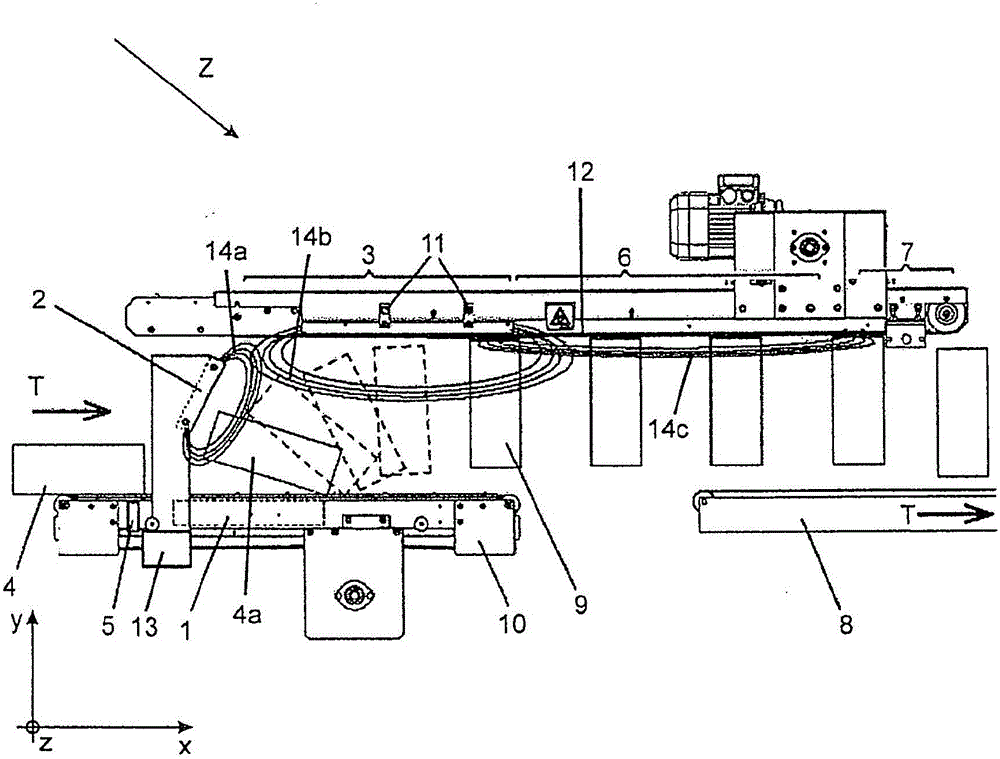
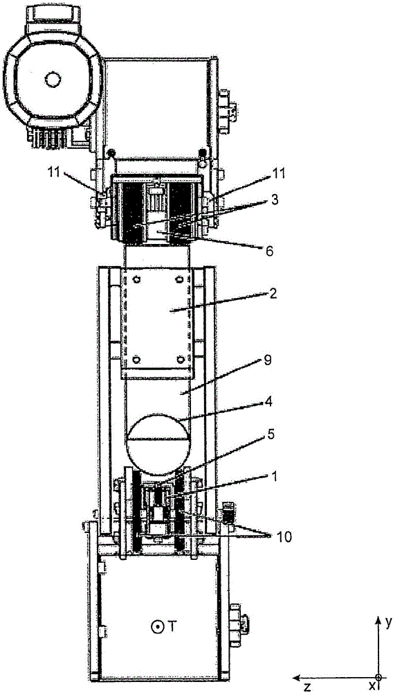
[0018] The different reference signs of the tank shall indicate the different state of the tank in terms of its orientation relative to the entry into the transport device 10 ( figure 1 ). Therefore, flat tanks are designated with reference number 4, tanks that are erected and transported in magnetic levitation are designated with reference number 9 and the tanks in the transition phase between the flat state and the erected state are designated with reference number 4a.

[0019] The concept "releasable" in relation to the magnet means here that the magnetic field strength of the magnet is only so strong that the canister within the range of the magnet can be lifted or lifted by a predefined external force, or the canister does not exist . Correspondingly, “fixable” means that the magnetic field strength of the magnet is so strong that the canister within the range of action of the magnet cannot be lifted or lifted by a predefined external force. In ...


PUM


Abstract

A magnetic can-body standing-up apparatus (Z) comprises an inlet transporting device (10) for conveying lying can bodies (4), a transporting device (12) arranged above the inlet transporting device (10) for conveying upright can bodies (9) hanging on the transporting device (12), and a controller (13). A first magnet arrangement (1) which is activatable and deactivatable in a manner controllable by the controller (13) is arranged below the inlet transporting device (10) in such a manner that a can body (4) lying on the inlet transporting device (10) is magnetically securable in a releasable manner on the inlet transporting device (10). A second magnet arrangement (2) is arranged above a region of the inlet transporting device (10) in which the can bodies are transported and is configured in such a manner that a can body (4) lying on the inlet transporting device (10) can be lifted up by means of the magnetic field of the second magnet arrangement (2) when the magnetic field of the first magnet arrangement (1) is deactivated. A third magnet arrangement (3) is provided above the transporting device (12) and is configured and arranged in such a manner that a can body (4a) which has been lifted up can be lifted up further and can be lifted off the inlet transporting device (10) and can be transported upright hanging magnetically on the transporting device (12). The controller (13) is configured in order to activate the first magnet arrangement (1) when a front edge of a can body (4) lying on the inlet transporting device (10) passes the second magnet arrangement (2) and in order to deactivate the first magnet arrangement (1) when a trailing edge of said can body (4) comes to lie under the second magnet arrangement (2).

Description

[0001] Description of the file [0002] This document claims the priority of Swiss Patent Application No. 0666 / 14 filed on May 5, 2014, for which the entire content is incorporated by reference. Technical field [0003] The present invention relates to a magnetic tank erecting device according to the independent claims and a device for manufacturing tanks comprising such a tank erecting device. Background technique [0004] When the can body is manufactured, after the can leaves the welding machine, the can is directly processed further or the applied seam cover is baked. For subsequent operations, the flat tank is usually placed in an upright vertical position. Tank erectors are known, where this is done by means of a magnetic field. Here, erection usually takes place around the front edge of the tank, so that the rear of the tank moves upward. Known magnetic can standers work with magnet boxes, which are arranged on both sides of the transport path of the can. [0005] An exampl...

Claims


Application Information

Patent Timeline
Patent Type & Authority Applications(China)
IPC IPC(8): B65G21/20B65G47/252
CPCB65G21/2018B65G47/252B65G2201/0252B65G47/2445B65G21/2009B65G15/105B65G15/58B65G47/24B65G47/36
Inventor P·高赫P·泰阿纳
Owner SOUDRONIC
Learn More