Fuel pump

A fuel pump and fuel technology, which is applied in the direction of pumps, fuel injection devices, liquid fuel feeders, etc., can solve the problems of poor fuel pump efficiency and delivery volume, and achieve the effect of compact structure

Inactive Publication Date: 2017-02-22
ROBERT BOSCH GMBH
View PDF5 Cites 1 Cited by
  • Summary
  • Abstract
  • Description
  • Claims
  • Application Information

AI Technical Summary

Problems solved by technology

This can lead to poor efficiency of the fuel pump or ev

Method used


Image

  • Fuel pump
  • Fuel pump
  • Fuel pump

Examples


Embodiment Construction

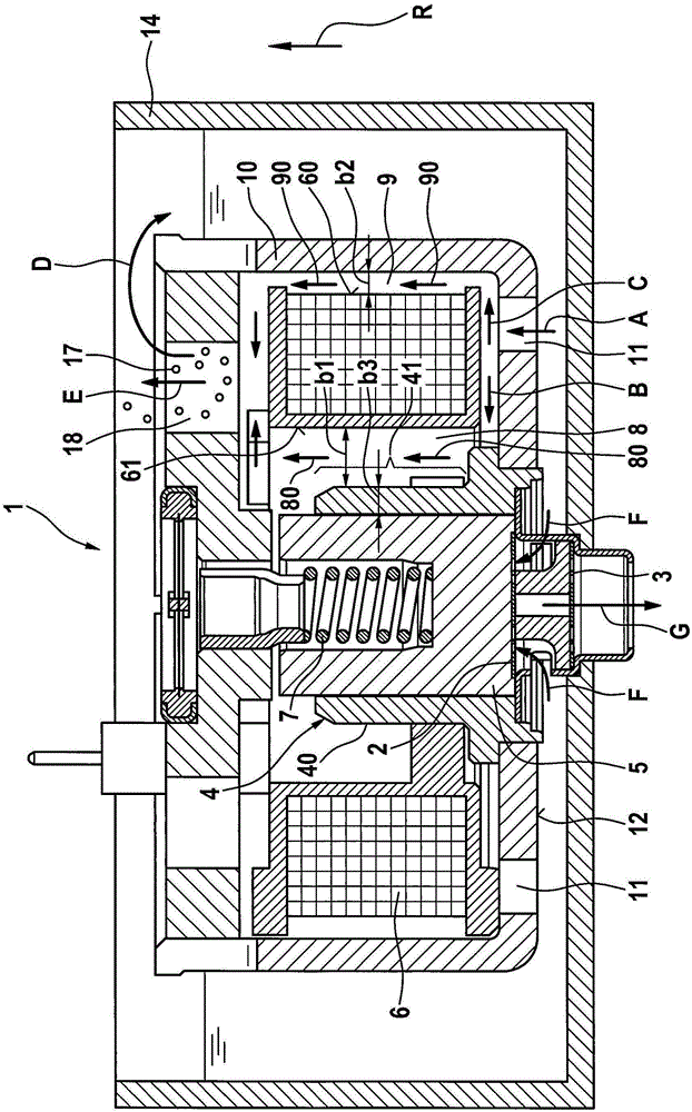
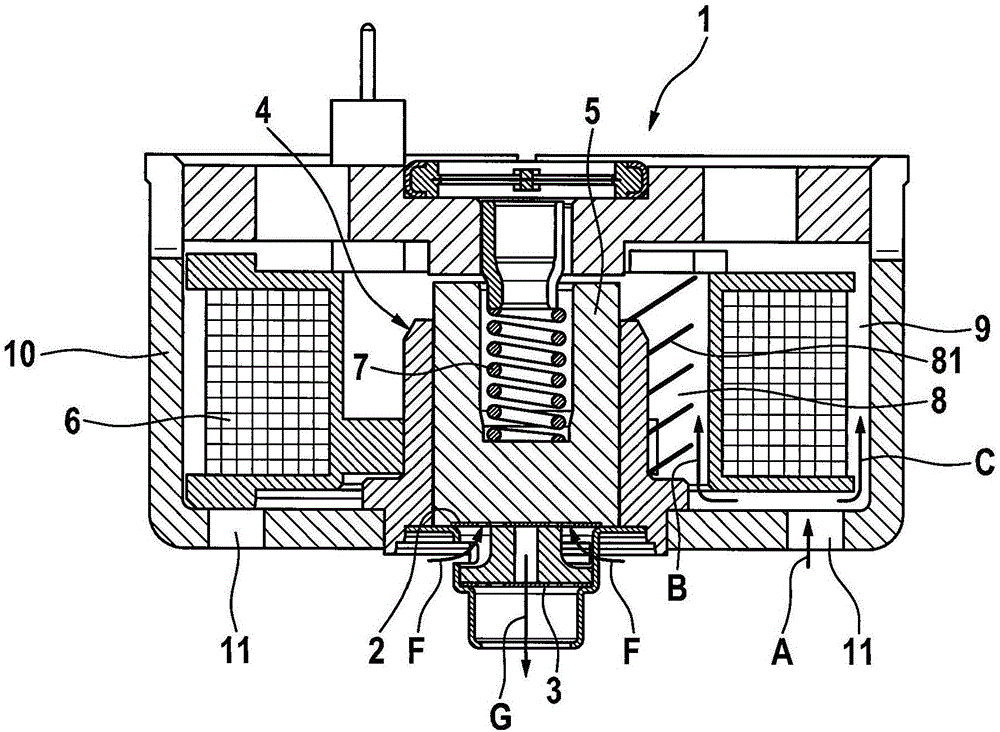
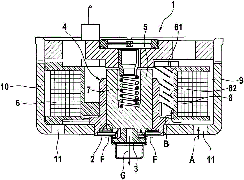
[0028] reference later figure 1 A fuel pump 1 according to a first preferred embodiment of the present invention will be described in detail. In addition, according to figure 1 The method according to the invention for operating the fuel pump 1 is described.

[0029] From figure 1 It can be seen that the fuel pump 1 according to the invention has: an inlet valve 2; an outlet valve 3; a cylinder 4; a piston 5 arranged in the cylinder 4; a heat-generating actuator 6 for actuating the piston 5; and a reset element 7 in the form of a helical spring for returning the piston 5 to its original position. The fuel pump 1 is installed in a fuel tank 14 .

[0030] The heat-generating actuator 6 is designed as a solenoid coil in this embodiment of the fuel pump according to the invention. Also conceivable as actuators are, for example, piezoelectric actuators or magnetostrictive actuators.

[0031] The fuel pump 1 according to the invention also has a housing 10 which is provided wi...


PUM


Abstract

The present invention relates to a fuel pump for conveying fuel, comprising an inlet valve (2), an output valve (3), a cylinder (4), a piston (5), said piston being arranged in the cylinder (4), a heat-generating actuator (6) for activating the piston (5), and a returning element (7) for returning the piston (5) into an initial position. According to the invention, the fuel pump (1) comprises a first gap (8) which is configured between the cylinder (4) and the heat-generating actuator (6), wherein a first fuel path (80) runs through the first gap (8). The invention further relates to a method for operating a fuel pump (1) according to the invention.

Description

technical field [0001] The invention relates to a fuel pump for delivering fuel, which can be used, for example, in vehicles, in particular motorcycles. A further aspect of the invention also relates to a method for operating such a fuel pump. Background technique [0002] Such a fuel pump is known for example from GB 2478876B. This relates to a fuel pump in the form of an electromagnetic piston pump having: an inlet valve; an outlet valve; a delivery chamber for delivering fuel; a piston arranged in a cylinder; an actuator in the form of an electromagnetic coil for manipulating the piston; and a reset element for resetting said piston to its original position, wherein the heat-generating actuator is arranged directly on the cylinder. This configuration has the disadvantage that the waste heat of the actuator is transferred directly to the cylinder and thus also to the fuel located in the delivery chamber. As a result, the fuel located in the delivery chamber heats up and...

Claims


Application Information

Patent Timeline
IPC IPC(8): F02M37/04F02M37/10F02M51/04F04B17/04F04B53/10F02M31/125
CPCF02B61/02F02M31/125F02M37/043F02M37/10F02M51/04F04B17/048F04B53/109Y02T10/12
Inventor S·芙洛F·尼切T·阿尔盖尔A·普利施A·克劳泽A·古切尔A·克鲁舍W·莫伊雷尔
Owner ROBERT BOSCH GMBH
Why Eureka
Try Eureka