Rotor shaft with a laminated core

A lamination stack and lamination technology, applied in the manufacture of stator/rotor body, magnetic circuit rotating parts, magnetic circuit shape/style/structure, etc. To achieve the effect of small damage and increased stiffness

Active Publication Date: 2017-02-22
THYSSENKRUPP PRESTA TECCENTER AG
View PDF10 Cites 9 Cited by
  • Summary
  • Abstract
  • Description
  • Claims
  • Application Information

AI Technical Summary

Problems solved by technology

The disadvantage is that the electromagnetic effect of the laminations is compromised at the joint diameter
In addition, the stresses acting at the joints on the inner diameter of the lamination stack connected by an interference fit influence the material properties and thus the function of the magnetic discs
[0007] It should be noted with regard to the design of the rotor of a synchronous motor that permanent magnets made of brittle material are embedded in the stack of laminations, which can be damaged due to the stresses generated by the interference fit

Method used


Image

  • Rotor shaft with a laminated core
  • Rotor shaft with a laminated core
  • Rotor shaft with a laminated core

Examples


Embodiment Construction

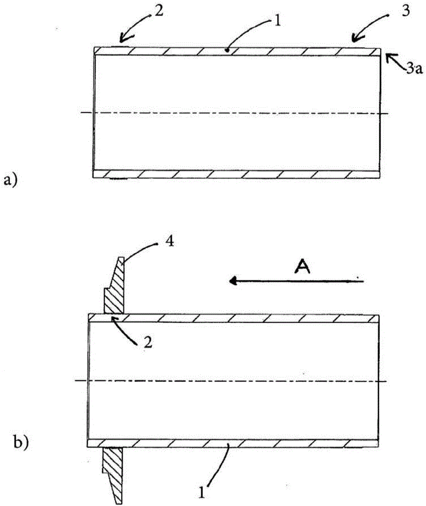
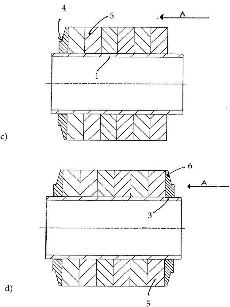
[0028] in figure 1 In, four initial method steps a) to d) for mounting the laminations on the hollow shaft 1 arranged as a rotor for a motor are shown. First of all, according to figure 1 In the first step of a, the surface of the hollow shaft 1 at the first sub-part 2 and the second sub-part 3 is increased by the rolling treatment of the outer surface profile—in this case, the thread with zero pitch. .

[0029] After being made into a finished product, the enlarged part can be ground to the final size. In the subsequent step 1b, the thrust washer 4 forming the stopper is slid onto the pre-assembled hollow shaft 1 in the direction of arrow A to be positioned on the rolling embossing, and then the thrust washer 4 is pressed to On the rolled first sub-part 2. In doing so, the wall of the hole in the thrust washer 4 is also roughened by the thread, which has a shallower depth than the outer surface profile of the sub-part 2. Trim the hole from the inside in this way The thrust w...


PUM


Abstract

The invention relates to a method for assembling laminations (5) on a shaft (1) of a rotor which is provided for an electric machine. The laminations (5) are pushed onto the shaft (1) in a sliding manner and are clamped between two pressure disks (4, 6) which are rotationally fixed to the shaft (1). The laminations (5) are pushed onto the shaft and rest against a stop (4) which is formed by a first pressure disk (4) that is arranged in a first sub-section (2) of the shaft (1). The second pressure disk (6) is pressed onto a second axial sub-section (3) of the shaft (1) in a force-fitting manner, thereby axially clamping the laminations (5), after the surface of the second axial sub-section (3) has been expanded by introducing an outer surface profile.

Description

Technical field [0001] The present invention relates to a method for mounting laminations on a shaft for a rotor of an electric motor, wherein the laminations are smoothly slid onto the shaft and clamped in anti-rotational manner between two thrusters connected to the shaft Between the washers. The invention also relates to a rotor with such a shaft and a motor with said shaft, especially an induction motor (Asynchron motor) or a permanent magnet synchronous motor. Background technique [0002] Many such rotors with laminations arranged thereon are known in the prior art, and most of these laminations are more or less stamped laminations. These rotors are used in asynchronous motors and permanent magnet synchronous motors. For rotors known in the prior art, additional elements such as axial tie rods, form-locking devices (Formschlussmittel) or other useful methods such as adhesives are usually used to create a reliable connection for torque transmission between the lamination s...

Claims


Application Information

Patent Timeline
Patent Type & Authority Applications(China)
IPC IPC(8): H02K1/22H02K1/28
CPCH02K1/22H02K1/28H02K15/02
Inventor 丹尼尔·保罗尤尔根·穆塞尔凯·哈迈尔托马斯·哈罗德泰奥菲尔-克里斯蒂安·安德烈
Owner THYSSENKRUPP PRESTA TECCENTER AG
Why Eureka
Try Eureka