Method and arrangement for uplink transmission adaptation

A link and data transmission technology, applied in the direction of transmission modification based on link quality, adjustment of transmission mode, error prevention/detection using the return channel, etc., can solve the problems of unable to transmit by UE, unable to control channel decoding, etc. Effect of Large System Throughput

Active Publication Date: 2017-02-22
TELEFON AB LM ERICSSON (PUBL)
View PDF5 Cites 8 Cited by
  • Summary
  • Abstract
  • Description
  • Claims
  • Application Information

AI Technical Summary

Problems solved by technology

[0050] When no ACK / NACK is received although the UE is scheduled, when a CQI report is missing, or when the UE is not transmitting despite a scheduling request and has requested resources, the base station may, for example, assume that the UE is not yet able to assign the control channel ( PDCCH) decoding, or the base station is not yet able to decode the transmission [PUCCH (Physical Uplink Control Channel) or PUSCH (Physical Uplink Control Channel)] made by the UE]

Method used


Image

  • Method and arrangement for uplink transmission adaptation
  • Method and arrangement for uplink transmission adaptation
  • Method and arrangement for uplink transmission adaptation

Examples


Embodiment Construction

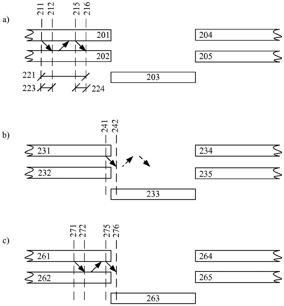
[0094] In the following, embodiments will be described in which a wireless communication device can adjust its uplink transmissions in response to an upcoming transmit / receive gap. In some embodiments, adjustments may be aimed at limiting any impact of such gaps autonomously established by the wireless communication device.

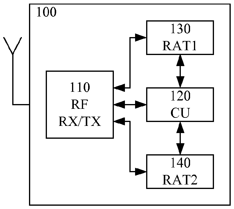
[0095] As will be appreciated, embodiments may be particularly suitable for use in applications such as Figure 1A An example wireless communication device 100 or Figure 1B The example wireless communication device 100b is used in the architecture of the device, wherein the first and second radio access control units 130, 140 are respectively adapted to control the communication with the first network node and the second radio access system of the first radio access system operation of a wireless communication device associated with a second network node of the access system, and wherein the radio control unit 120 is adapted to manage the time sharing of...


PUM


Abstract

A method of a wireless communication device is disclosed wherein the wireless communication device comprises a radio transceiver, first (310) and second (330) autonomous radio access control units, and a radio control unit (320). The first and second autonomous radio access control units are adapted to control operation of the wireless communication device in association with a first network node of a first radio access system and a second network node of a second radio access system, respectively, and the radio control unit is adapted to manage time sharing of the radio transceiver by the first and second radio access control units. The method comprises during use (311) of the radio transceiver by the first radio access control unit-receiving (by the radio control unit) a first message (332) from the second radio access control unit and sending (by the radio control unit) a second message (322) to the first radio access control unit. The first message indicates a timing of an upcoming gap in the use of the radio transceiver by the first radio access control unit, wherein the timing of the upcoming gap is autonomously established (331) by the second radio access control unit. The second message causes adaptation (316) of a planned uplink transmission by the first radio access control unit if (315) a reception by the radio transceiver of an expected response to the planned uplink transmission coincides with the timing of the upcoming gap. Corresponding computer program product, arrangement and wireless communication device are also disclosed.

Description

technical field [0001] The invention generally relates to the field of wireless communication devices in which a radio transceiver is shared by a first and a second radio access control unit. More specifically, it relates to the handling of gaps during use of a radio transceiver by a first radio control unit, wherein gaps are autonomously established by a second radio access control unit (or vice versa). Background technique [0002] Figure 1A A portion of an example wireless communication device 100 is schematically shown, wherein a radio transceiver (RFRX / TX) 110 is shared (in time) by first and second radio access control units (RAT1 , RAT2 ) 130 , 140 . A control unit (CU) 120 manages time sharing according to requests (with various attributes) from the first and second radio access control units. [0003] In this type of implementation of wireless communication, various problems may arise related to the situation where both radio access control units request access to...

Claims


Application Information

Patent Timeline
Patent Type & Authority Applications(China)
IPC IPC(8): H04W72/12H04W52/38H04L1/00H04L1/18
CPCH04L1/1671H04L1/1861H04L1/0003H04L1/0015H04W72/1215H04L1/0006H04L1/18H04W88/02
Inventor B.林多夫J.阿克蒙
Owner TELEFON AB LM ERICSSON (PUBL)
Why Eureka
Try Eureka