Slit detection device and detection method

A detection device and detection method technology, which are applied to measurement devices, optical devices, image data processing, etc., to achieve the effects of reducing missed detection rate, increasing robustness, and improving fitting and positioning accuracy

Inactive Publication Date: 2017-03-01
ZHEJIANG ICARE VISION TECH
View PDF8 Cites 7 Cited by
  • Summary
  • Abstract
  • Description
  • Claims
  • Application Information

AI Technical Summary

Problems solved by technology

For the detection of gap changes between the railway track slab and the subgrade base plate, it is required to detect 24 hours a day without interruption, and the existing gap detection devices and methods cannot meet this requirement

Method used


Image

  • Slit detection device and detection method
  • Slit detection device and detection method
  • Slit detection device and detection method

Examples


Embodiment Construction

[0025] The specific implementation of the gap detection device and detection method provided by the present invention will be described in detail below in conjunction with the accompanying drawings.

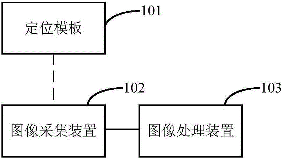
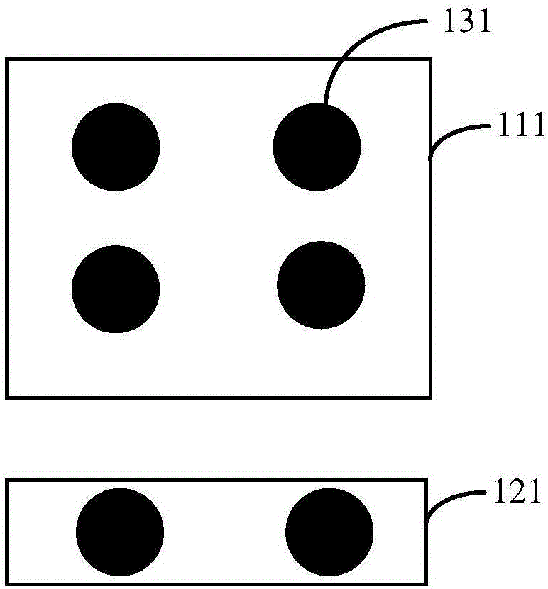
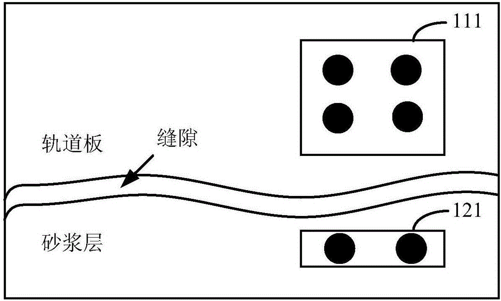
[0026] Please refer to figure 1 , is a gap detection device according to an embodiment of the present invention, including a positioning template 101, and the positioning template includes a number of marking points, which are used to set the gap position to be measured to locate the gap position to be measured; the image acquisition device 102 is used for It is arranged on the side of the gap to obtain the image of the area where the positioning template is located; the image processing device 103 is used to receive the image obtained by the image acquisition device, and process the image, confirm the image of the position of the template, and calculate the template according to the image of the position of the template The gap distance at the location.

[0027] The positioning...


PUM


Abstract

The invention provides a slit detection device and a detection method. The slit detection device comprises a positioning template, an image acquisition device and an image processing device. The positioning template comprises multiple marking points, and is arranged on a to-be-measured slit part and used for positioning a to-be-measured slit position. The image acquisition device is arranged on the side face of the slit position and used for acquiring an image of a region where the positioning template is arranged. The image processing device is used for receiving the image acquired by the image acquisition device, processing the image, determining the image of the region where the positioning template is arranged, and calculating the slit distance in the template position according to the image of the region where the positioning template is arranged. The slit detection device and the detection method are suitable for field installation and maintenance and the slit distance can be monitored in real time.

Description

technical field [0001] The invention relates to the field of intelligent detection, in particular to a gap detection device and a detection method. Background technique [0002] During the construction of the railway track, gaps are prone to appear in the mortar layer between the railway track slab and the subgrade slab. It is necessary to accurately locate and measure the gap for real-time monitoring to ensure the safety and reliability of the railway track. [0003] The existing common gap detection methods are divided into contact type and non-contact type. The contact type is suitable for active measurement occasions with high precision requirements, and the non-contact type mainly uses photosensitive devices or images for measurement. For example, the patent with the publication number CN101915551A: "A Pipe Gap Detection Tool" discloses a method for detecting gaps using photosensitive devices, and the patent with the publication number CN105651194A: "A Non-contact On-li...

Claims


Application Information

Patent Timeline
Patent Type & Authority Applications(China)
IPC IPC(8): G06T7/00G01B11/14
CPCG06T7/0004G01B11/14G06T2207/10004G06T2207/30132
Inventor 尚凌辉余天明王弘玥
Owner ZHEJIANG ICARE VISION TECH
Why Eureka
Try Eureka