Eureka AIR delivers breakthrough ideas for toughest innovation challenges, trusted by R&D personnel around the world.

Thickness design method of radome

A design method and radome technology, which are applied in computing, radiation unit housing, special data processing applications, etc., can solve problems such as difficulty in processing, drastic changes in radome wall thickness, and failure to consider radome gain and loss electrical performance indicators.

Active Publication Date: 2017-03-01
XIDIAN UNIV
View PDF6 Cites 17 Cited by
  • Summary
  • Abstract
  • Description
  • Claims
  • Application Information

AI Technical Summary

Problems solved by technology

The disadvantage of this method is that it does not consider the constraints on the wall thickness distribution, resulting in drastic changes in the wall thickness of the obtained radome, which is difficult to process and realize. In addition, it does not consider the gain loss of the radome, which is an important electrical performance index.

Method used

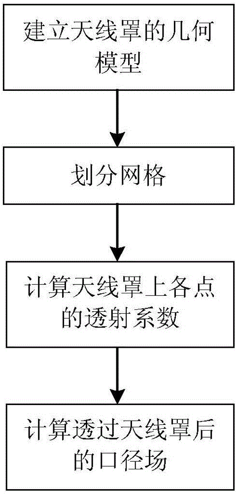

Image

  • Thickness design method of radome
  • Thickness design method of radome
  • Thickness design method of radome

Examples


Embodiment Construction

[0067] The present invention will be described in further detail below with reference to the accompanying drawings.

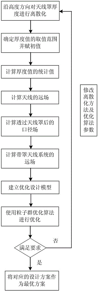
[0068] refer to figure 1 , the concrete steps of the present invention are as follows:

[0069] Step 1, the thickness of the radome is discretized according to the height direction of the radome.

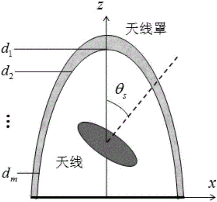
[0070] Such as figure 2 As shown, along the height of the radome, a coordinate system O-xyz is established with the center of the bottom surface of the radome as the origin and the bottom surface as the xy plane. The height of the radome is along the z direction, and 10 discrete points are evenly selected along this direction. for z 1 ,z 2 ,...,z 10 , in the figure θ s Indicates the scan angle of the antenna.

[0071] Step 2, determine the value range of the thickness value, and assign the initial value to the thickness at the discrete point.

[0072] (2a) The integrally formed aircraft radome usually adopts a half-wavelength wall thickness, and the calculat...


PUM


Abstract

The invention relates to a thickness design method of a radome. The method includes following steps: (1) performing discretization on the thickness of the radome according to the height direction of a radome body; (2) determining the value range of the thickness value, and giving an initial value to the thickness at a discrete point; (3) calculating a statistical value thereof according to the thickness value of the discrete point; (4) calculating a far field of an antenna, and extracting electrical performance indexes such as the gain G1 and the main beam position B1; (5) calculating a transmission coefficient of the random body, shown in the description, by employing a transmission line theory; (6) calculating a far field F' (theta, phi) of an antenna system with the radome, and drawing a far-field directional diagram; (7) establishing an optimization design model; and (8) determining whether the electric performance indexes and the thickness distribution of the random after optimization satisfy a preset requirement. According to the method, the electrical performance indexes of the radome are improved.

Description

technical field [0001] The invention belongs to the technical field of radar antennas, in particular to a method for designing the thickness of a radome, which can be used in the structural design of an aircraft radome. Background technique [0002] A radome is a wave-transparent shell that protects the antenna from the natural environment. It is a covering made of natural or artificial dielectric materials, or a specially shaped electromagnetic window composed of a dielectric shell supported by a truss. A well-designed radome, in addition to the functions of protection, conductivity, reliability, concealment and decoration, can also prolong the service life of each part of the entire system, reduce life costs and operating costs, simplify design, and reduce maintenance costs , Ensure the accuracy of the antenna surface and position, and create a good working environment for antenna operators. However, the radome will also affect the electromagnetic radiation of the ideal a...

Claims


Application Information

Patent Timeline
IPC IPC(8): H01Q1/42G06F17/50
CPCG06F30/13G06F30/367H01Q1/42
Inventor 许万业李鹏段宝岩张逸群宋立伟胡乃岗
Owner XIDIAN UNIV
Why Eureka
Eureka Blog
Learn More