
Automatic feeding and taking equipment with u-turning device

An automatic feeding and turning device technology, applied in the field of workpiece conveying devices, can solve the problems of long time for operators to adapt, high cost of construction, high maintenance cost, etc., and achieve low manufacturing cost, convenient installation and maintenance, and high degree of automation Effect

Active Publication Date: 2017-03-08
广东圣特斯数控设备有限公司
View PDF5 Cites 14 Cited by
  • Summary
  • Abstract
  • Description
  • Claims
  • Application Information

AI Technical Summary

Problems solved by technology

[0003] In addition, the existing manipulator structure uses the combination of the rotating seat and the multi-section structural arm to realize the retrieving and discharging of materials at different angles and heights, but the structure is complex, the application program debugging is repeated, and the operator needs to adapt for a long time Skilled operation, and high cost, high maintenance cost

Method used


Image

  • Automatic feeding and taking equipment with u-turning device
  • Automatic feeding and taking equipment with u-turning device
  • Automatic feeding and taking equipment with u-turning device

Examples


Embodiment Construction

[0050] The present invention will be further described below in conjunction with the accompanying drawings and embodiments.

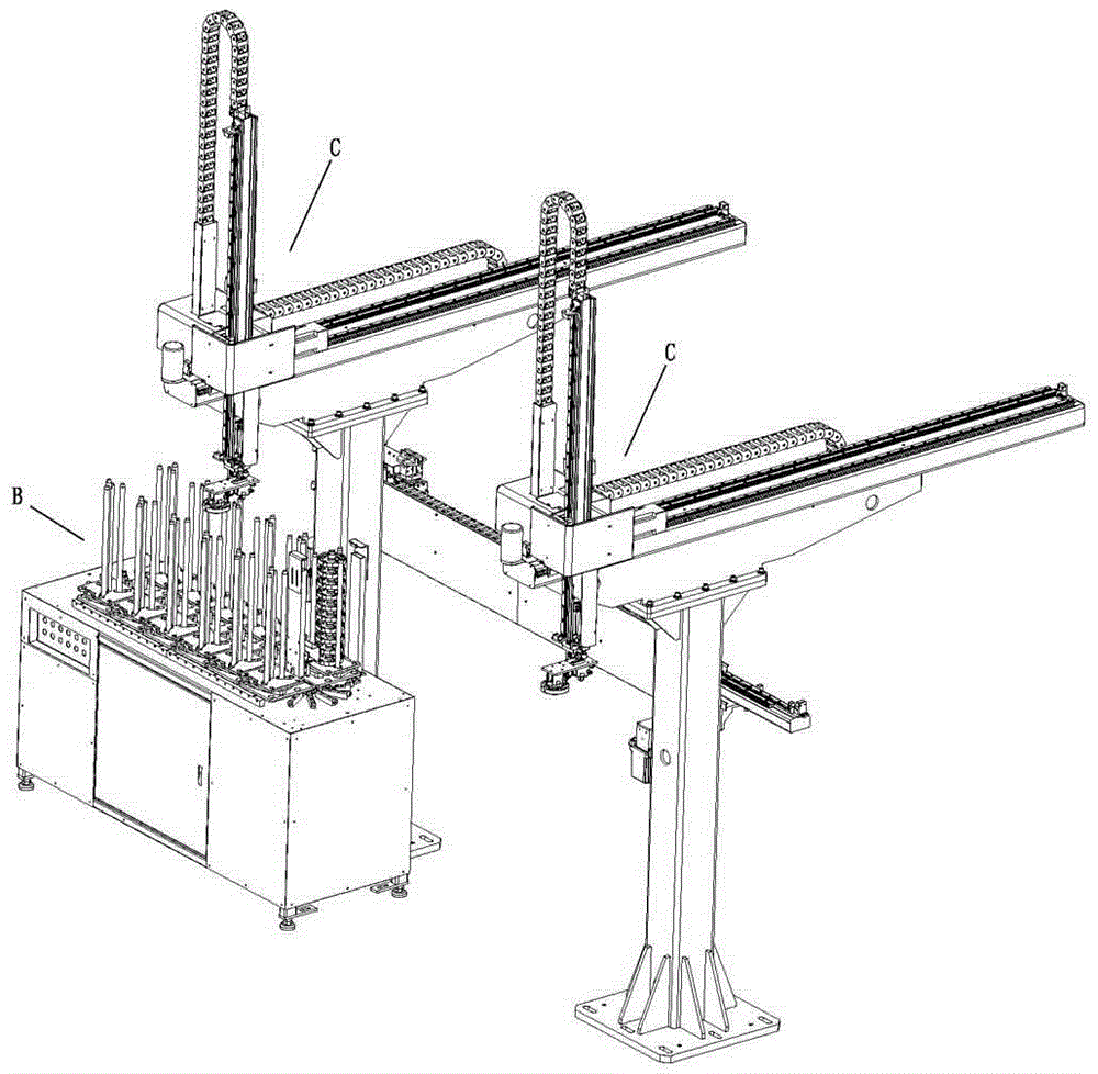
[0051] Such as Figure 1 to Figure 12 As shown, an automatic feeding and reclaiming device with a U-turn device includes a rotary bin B and two two-axis mechanical arms C, and a U-turn transfer device D is connected between the two two-axis mechanical arms C. It is characterized in that ;

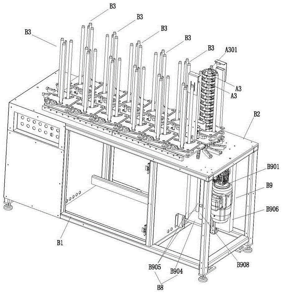
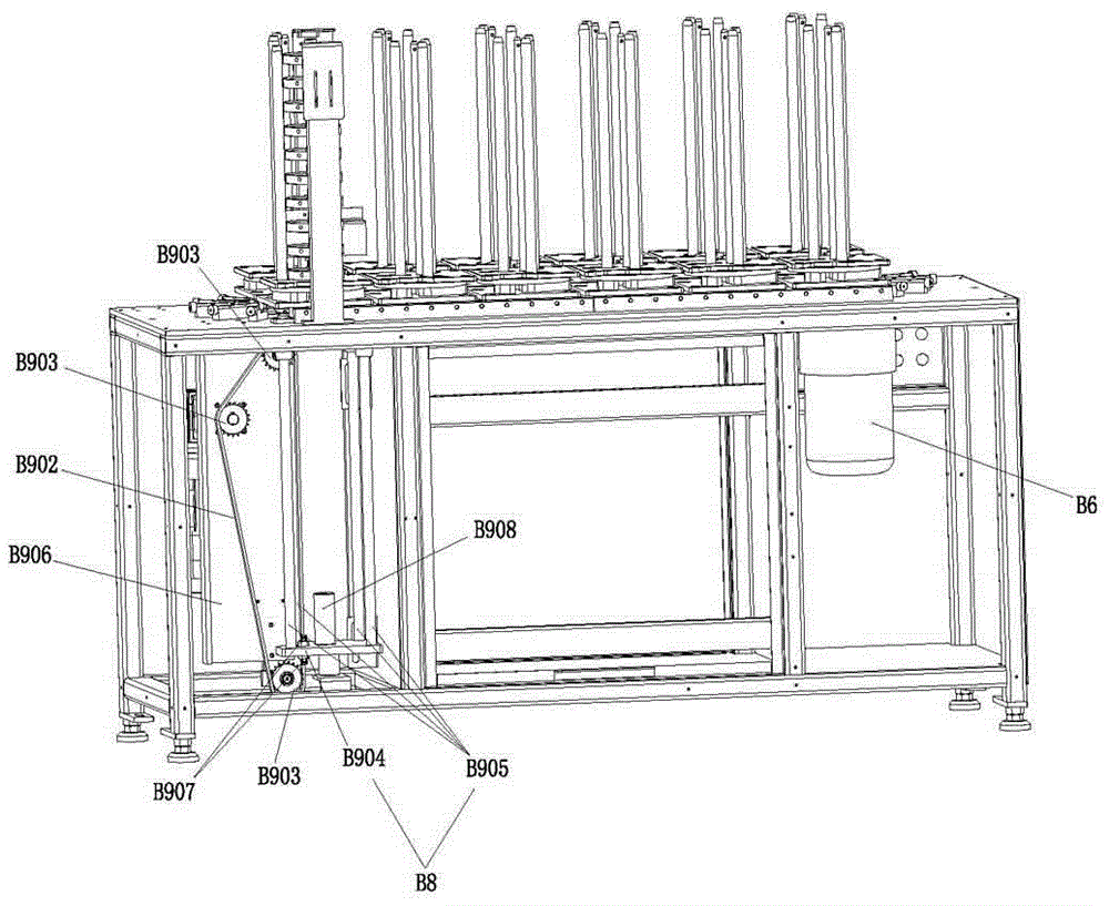
[0052] The rotary bin B includes a bin seat B1, and a workbench B2 is arranged on the top of the bin seat B1. A plurality of storage racks B3 are installed on the work table B2, and a plurality of workpieces A3 are stacked on each storage rack B3. The feature is that there are two transmission sprockets B4 on both sides of the workbench B2, and the two transmission sprockets B4 are connected by a transmission chain B5, and one of the transmission sprockets B4 is driven by a transmission sprocket motor B6;

[0053] A plurality of storage racks are arranged along the...


PUM


Abstract

The invention relates to automatic feeding and taking equipment with a u-turning device. The automatic feeding and taking equipment comprises a rotary type material bin and two two-shaft mechanical arms and a u-turning transferring device; the rotary type material bin comprises a material bin base, a working table is arranged at the top of the material bin base, a plurality of material storage frames are installed on the working table, and a plurality of workpieces are stacked on each material storage frame; two transmission chain wheels are arranged on the two sides of the working table correspondingly, the two transmission chain wheels are connected through a transmission chain, and one of the transmission chain wheels is driven by a transmission chain wheel motor; the multiple material storage frames are arranged in the layout extending direction of the transmission chain, each material storage frame is in connected fit with the transmission chain through a connecting assembly, and each material storage frame achieves movement along with transmission of the transmission chain; a lifting frame is installed in the material bin base and is driven by a lifting assembly, so that the lifting frame penetrates the working table to upwards lift the workpieces; and the multiple material storage frames are all arranged to be capable of moving along with the transmission chain, rotary workpiece conveying is formed, the storage capacity of the workpieces is effectively increased, and the machining efficiency is effectively improved.

Description

technical field [0001] The invention relates to the field of devices for conveying workpieces, in particular to an automatic feeding and reclaiming device equipped with a U-turn device. Background technique [0002] At present, in the existing CNC machining centers, the workpiece clamping generally requires manual loading and unloading, which leads to limited processing efficiency and low processing efficiency. However, the use of manipulators for loading and unloading is already the development of the industry. trend, while the structure of the manipulator has matured, and the movement of the manipulator arm is already very flexible. How to cooperate with the manipulator to effectively coordinate the storage side and the processing side is a problem to be solved in front of the engineers. [0003] In addition, the existing manipulator structure uses the combination of the rotating seat and the multi-section structural arm to realize the retrieving and discharging of materi...

Claims


Application Information

Patent Timeline
Patent Type & Authority Applications(China)
IPC IPC(8): B23Q7/04B23Q7/00
CPCB23Q7/00B23Q7/048
Inventor 周沃强萧耀荣罗锦伟周沃华
Owner 广东圣特斯数控设备有限公司
Learn More