Handheld tool and clamping device thereof
A technology of hand-held tools and clamping devices, which is applied in the direction of transmission devices, manufacturing tools, portable motorized devices, etc., and can solve problems such as disengagement, disassembly and assembly of working heads, etc.
- Summary
- Abstract
- Description
- Claims
- Application Information
AI Technical Summary
Problems solved by technology
Method used
Image
Examples
specific Embodiment approach 1
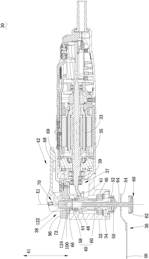
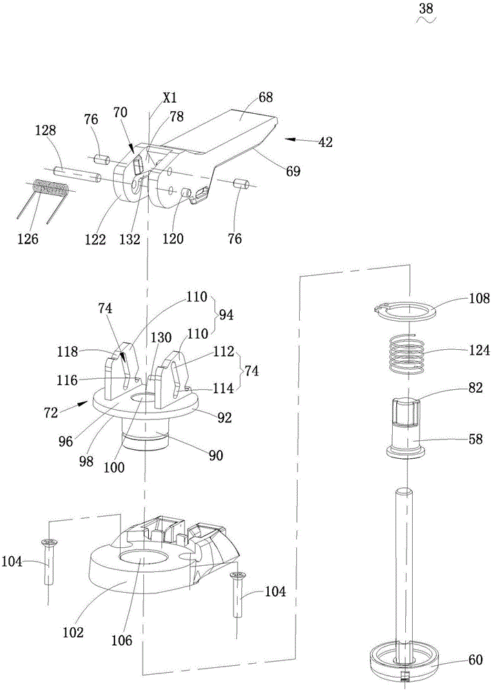
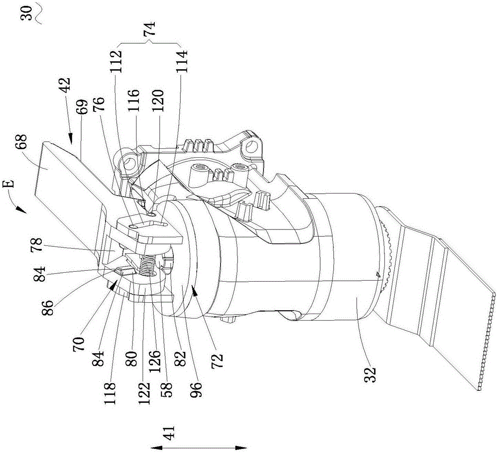
[0048] figure 1Shown is the multifunction machine 30 in this embodiment. This multifunctional machine 30 has a housing 32, an output shaft 34 extending from the inside of the housing 32, a working head 36 installed at the end of the output shaft 34, and a clamping device for fixing the working head 36 on the end of the output shaft 34 38. The clamping device 38 includes a clamping unit 40 and an operating assembly 42 , wherein the clamping unit 40 is used to clamp the working head 36 in the axial direction 41 , and the operating assembly 42 is used to drive the clamping unit 40 . The axial direction 41 extends substantially parallel to the axis X1 of the output shaft 34 .
[0049] When the multi-function machine 30 is working, the output shaft 34 performs a rotational and oscillating motion around its own axis X1, thereby generating a large abrupt torque along the two oscillating directions. Therefore, a very large axial clamping force is required to ensure that the above-m...
specific Embodiment approach 2
[0094] like Figure 10 As shown in the figure, the second embodiment of the present invention provides a multifunctional machine 200, which is the same as the multifunctional machine 30 in the first embodiment, including a housing 32 and an output shaft 34 extending from the inside of the housing 32 , the working head 36 installed at the end of the output shaft 34 , and the clamping device 238 for fixing the working head 36 at the end of the output shaft 34 . The clamping device 238 includes a clamping unit 40 and an operating assembly 242 , wherein the specific structures and principles of the clamping unit 40 and the operating assembly 242 are basically the same as those of the first embodiment, and the following description will mainly focus on the structures that differ from the first embodiment.
[0095] See Figure 11 The difference between this embodiment and the first embodiment is the installation position of the elastic element 226 disposed between the installation ...
specific Embodiment approach 3
[0110] Figure 17 to Figure 20 It is the third embodiment of the present invention. See Figure 17 and Figure 18 , the third embodiment provides a multifunctional machine 300, which is basically the same as the multifunctional machine 30 in the first embodiment, including a housing 32, an output shaft 34 extending from the inside of the housing 32, and an output shaft 34 installed on the output shaft 34. The working head 36 at the end and the clamping device 338 for fixing the working head 36 on the end of the output shaft 34 .
[0111] In this embodiment, see Figure 17 and Figure 18 , the clamping device 338 includes a clamping unit 340 and an operating assembly 342, wherein the basic principle of the clamping unit 340 and the operating assembly 342 is the same as that of the first embodiment, but the specific structure is different from the first embodiment.
[0112] The operating assembly 342 includes an operating member 368 and a driving member 370 . The operating...
PUM
 Abstract
Description
Claims
Application Information
 - R&D
- Intellectual Property
- Life Sciences
- Materials
- Tech Scout
- Unparalleled Data Quality
- Higher Quality Content
- 60% Fewer Hallucinations
Browse by: Latest US Patents, China's latest patents, Technical Efficacy Thesaurus, Application Domain, Technology Topic, Popular Technical Reports.
© 2025 PatSnap. All rights reserved.Legal|Privacy policy|Modern Slavery Act Transparency Statement|Sitemap|About US| Contact US: help@patsnap.com


