
A constant-contact method for preventing steel spring from breaking and vertical stop

A vertical stop, steel spring technology, applied in the direction of bogies, railway car body parts, axle box installation, etc., can solve the problem of greatly improving the fracture resistance of steel springs, without adjusting the stiffness, and it is difficult to effectively reduce the steel spring metal Fatigue and other problems, to achieve the effect of tight structure, reducing wear and preventing steel spring from breaking

Active Publication Date: 2018-09-07
ZHUZHOU TIMES RUIWEI ANTI VIBERATION EQUIP LTD
View PDF9 Cites 0 Cited by
  • Summary
  • Abstract
  • Description
  • Claims
  • Application Information

AI Technical Summary

Problems solved by technology

It can be seen that the various elastic buffer devices in the above-mentioned patents do not have a structure to adjust the variable stiffness, and the adjustment of the stiffness is also limited due to their simple structure, so it is difficult to effectively reduce the metal fatigue of the steel spring, and it is still difficult to greatly improve the stiffness of the steel spring. The ability of the spring to resist fracture, so how to prevent the fracture of the steel spring more effectively needs to be further explored

Method used


Image

  • A constant-contact method for preventing steel spring from breaking and vertical stop
  • A constant-contact method for preventing steel spring from breaking and vertical stop
  • A constant-contact method for preventing steel spring from breaking and vertical stop

Examples


Embodiment 1

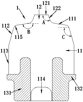
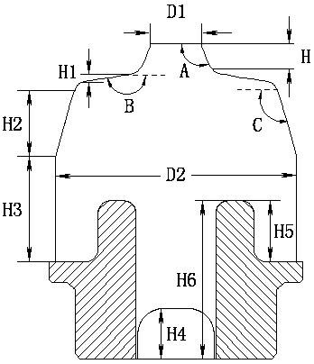
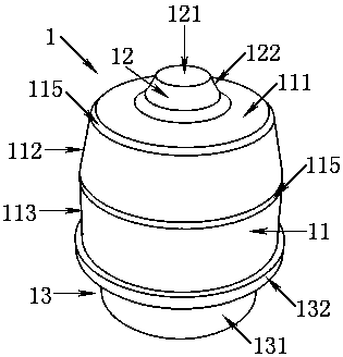
[0041] Such as Figure 5 As shown, a positioning base 4 is fixed above the axle box 5, and a double-volume spiral steel spring 2 is arranged above the positioning base 4, and the steel spring 2 supports the weight of the locomotive above the bogie frame 6. In order to reduce the vertical load borne by the steel spring 2 and reduce the metal fatigue generated by the steel spring 2 during locomotive operation, thereby preventing the steel spring 2 from breaking, a vertical stop 1 is provided in the steel spring 2 . The base flange 132 of the vertical stop 1 abuts against the positioning base 4 , and since the vertical stop 1 and the positioning base 4 are both revolving bodies, the vertical stop 1 can be stuck in the positioning base 4 . A frame guide cylinder 3 is arranged directly above the vertical stop 1. When the locomotive is unloaded, the rubber boss 12 of the vertical stop 1 is in contact with the frame guide cylinder 3, and the locomotive moves from no load to the maxim...

Embodiment 2

[0063] Such as Figure 6 As shown, the difference from Embodiment 1 is that the rotator-shaped rubber boss 12 above the rubber body 11 is no longer conical, but the generatrix 123 of the rotator-shaped rubber boss 12 is outward. Extruded smooth curves. Such as Figure 7 As shown, the diameter D3 of the rubber boss 12 refers to the diameter of the bottom of the rubber boss 12 , which is different from the diameter D1 of the rubber boss 12 in Embodiment 1, which refers to the diameter of the top of the rubber boss 12 . The preferred value of the diameter D3 of the rubber boss 12 in this embodiment is 20mm-60mm.

[0064] The busbar 123 is a gyratory-shaped rubber boss 12 protruding outwards with a smooth curve. When the locomotive load increases and the frame guide cylinder 3 is pressed down, the stiffness curve of the vertical stop 1 can be made smoother, thereby It can more effectively prevent the rigidity of the vertical stop 1 from increasing suddenly, and can better absor...


PUM


Abstract

A vertical backstop for preventing steel spring break, wherein the vertical backstop (1) is located in the steel spring (2), characterized in that the vertical backstop (1) comprises a rubber main body (11), a rubber convex platform (12) and a pedestal (13), wherein a revolve solid shaped rubber convex platform (12) is provided above the rubber main body (11), the rubber main body (11) is provided with an annular straight section and an annular arc section (115), the rubber convex platform (12) is connected with the rubber main body (11) via the annular arc section (115), a pedestal (13) is provided underneath the rubber main body (11), and the bottom of the rubber main body (11) is provided with a cavity (114), wherein the rubber main body (11), the rubber convex platform (12) and the pedestal (13) are an entirety.

Description

technical field [0001] The invention relates to a buffer device used on a locomotive, in particular to a vertical stop for a buffer locomotive primary suspension system. Background technique [0002] At present, in the manufacturing process of railway locomotives, spring devices are widely used for bearing and vibration reduction. As a key component of locomotives, springs have an important impact on the dynamic performance and running quality of locomotives. With the implementation of railway speed-up and heavy-duty strategy, the number of failures affecting the running performance of locomotives due to broken springs has gradually increased, and the running stability of locomotives has deteriorated, which has caused hidden dangers to traffic safety. [0003] The steel spring directly above the locomotive axle box is one of the main parts of the bogie, and the steel spring bears the weight of the locomotive above the bogie frame. The stiffness of the vertical force transmi...

Claims


Application Information

Patent Timeline
Patent Type & Authority Patents(China)
IPC IPC(8): B61F5/50B61F5/30
CPCB61F5/301B61F5/305
Inventor 冯万盛罗俊李斌肖祥龙陈俊辉曾慧
Owner ZHUZHOU TIMES RUIWEI ANTI VIBERATION EQUIP LTD
Learn More