
Composite coating and marker

A composite coating and marking technology, applied in the field of electric power, can solve the problems of easily pasted small advertisements and high breakage rate of signs, and achieve the effect of solving the problems of pasting and clearing, improving tear resistance and good anti-breakage performance.

Active Publication Date: 2017-03-08
STATE GRID BEIJING ELECTRIC POWER +1
View PDF4 Cites 1 Cited by
  • Summary
  • Abstract
  • Description
  • Claims
  • Application Information

AI Technical Summary

Problems solved by technology

[0003] The main purpose of the present invention is to provide a composite coating and a sign to solve the problems that the existing signs have a high rate of damage and are easily pasted with small advertisements

Method used


Image

  • Composite coating and marker
  • Composite coating and marker
  • Composite coating and marker

Examples


preparation example Construction

[0031] The preparation method of the above-mentioned coating can be sprayed. Specifically, each layer is sprayed on the base material in sequence, and after being cured, it can be formed.

[0032] In addition, the present invention also provides a sign, which comprises the above-mentioned composite coating. In the actual application process, the above-mentioned composite coating can be directly used as a mark.

[0033] The above-mentioned marking provided by the present invention includes the above-mentioned composite coating. The raw materials of the sealing layer include 36-77 parts of water, 0.9-2.2 parts of the first pH regulator, and 22-61 parts of toughening agent. This layer is in direct contact with the base material on which the logo is attached, and has high tear resistance. Therefore, the tear resistance of the coating can be significantly improved. Using this coating as an anti-collision logo has good anti-damage performance. The above-mentioned coating also incl...

Embodiment 1 to 6

[0042] Composite coating manufacturing process:

[0043] Configure the raw paint for the sealing layer, rough layer and finish layer, use the pole as the base material, and spray the sealing primer coating on the base material by spraying. After curing, further spray the rough layer paint. After the rough layer is cured, further spray the varnish coating, and solidify to form a composite coating.

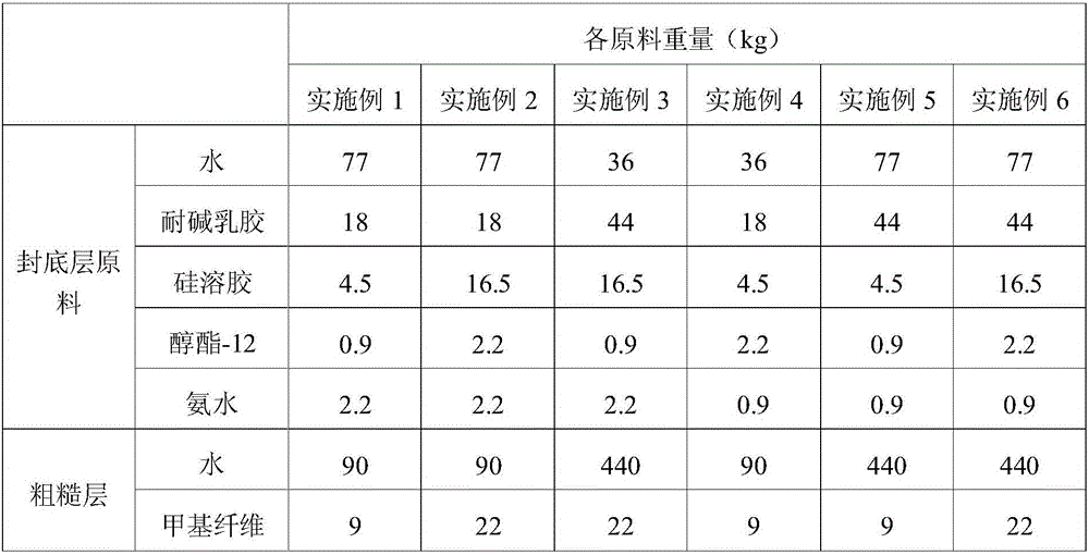
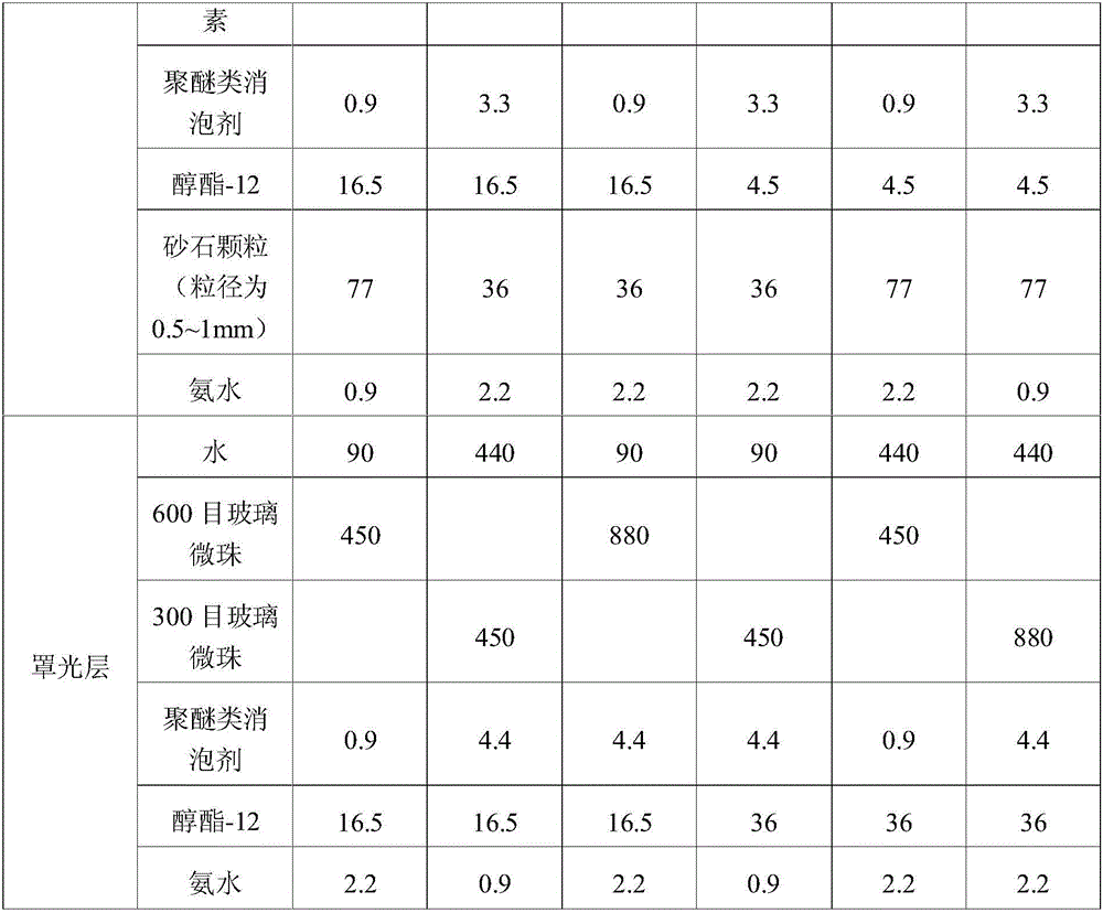
[0044] The coating material of each embodiment is as shown in Table 1:

[0045] Table I

[0046]

[0047]

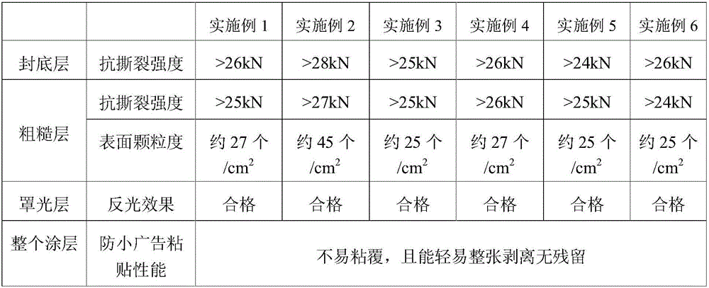
[0048] The performance characterization results of each layer of the composite coating in Examples 1 to 6 are shown in Table 2:

[0049] Table II

[0050]

[0051] From the above description, it can be seen that the above-mentioned embodiments of the present invention achieve the following technical effects: each layer of the composite coating prepared in the above-mentioned embodiments has high tear resistance. At the same time, it can prevent small advertisements...


PUM


Abstract

The invention provides a composite coating and a marker. The composite coating comprises a bottom sealing layer and a rough layer, wherein the bottom sealing layer covers a substrate material; the bottom sealing layer is prepared from the raw materials in parts by weight: 36 to 77 parts of water, 0.9 to 2.2 parts of a first pH (Potential of Hydrogen) regulator and 22 to 61 parts of a toughening agent; the rough layer is located at one side, far away from the substrate material, of the bottom sealing layer; the quantity of bulges on the surface of the rough layer is 25 / cm<2> to 45 / cm<2>. The bottom sealing layer has relatively high tear resistance strength so that the tear resistance performance of the whole coating can be obviously improved; an anti-collision marker utilizing the coating has good breakage-proof performance. The quantity of the bulges on the surface of the rough layer is 25 / cm<2> to 45 / cm<2>, so that the surface of the coating has obvious roughness; when the coating is used as the marker, adlets are not easy to stick on the surface of the marker and the adlets stuck on the surface are also very easily removed as a whole. Therefore, the problems of sticking and removing the adlets on the marker can be solved.

Description

technical field [0001] The invention relates to the field of electric power, in particular to a composite coating and marking. Background technique [0002] Existing electric poles use thin PVC material to stick anti-collision signs, which are easily pasted by small advertisements, and are easily damaged when sanitation workers remove small advertisements, resulting in a high rate of damage to existing anti-collision signs. Contents of the invention [0003] The main purpose of the present invention is to provide a composite coating and a sign to solve the problems that the existing signs have a high rate of damage and are easily pasted with small advertisements. [0004] In order to achieve the above object, one aspect of the present invention provides a composite coating, which includes: a sealing layer, covered on the base material, and the raw materials of the sealing layer include 36 to 77 parts of water and 0.9 to 2.2 parts of water in parts by weight. The first pH ...

Claims


Application Information

Patent Timeline
IPC IPC(8): C09D1/00C09D7/12C09D201/00C09D5/33C09D5/08G09F3/00
Inventor 朱艳霞黄烁于爽徐剑郭莹
Owner STATE GRID BEIJING ELECTRIC POWER
Learn More