
General template for pulling pieces and pulling rods and template system

A general formwork and tie-rod technology, which is applied to formwork/formwork components, formwork/formwork/work frame connectors, and on-site preparation of building components. It can solve incompatibility, high positioning accuracy requirements, and poor quality. It can solve the problems of sheet system, etc., to achieve the effect of force and deformation synergy, uniform force and reasonable effect.

Active Publication Date: 2017-03-08
SHENZHEN RILI TECH CO LTD
View PDF10 Cites 5 Cited by
  • Summary
  • Abstract
  • Description
  • Claims
  • Application Information

AI Technical Summary

Problems solved by technology

The formwork of the above two systems has its own advantages and disadvantages: the concrete members formed by the formwork of the pull-tie system are accurate in size, easy to install, and relatively good in construction quality, but the pull-tab system requires high positioning accuracy, and it is difficult to use it in large concrete members with dense steel bars ;Tie rod system formwork is more flexible in use and has a wide range of applications, but its quality control is not as good as that of the pull sheet system
The two systems are currently incompatible, and engineering applications are used separately

Method used


Image

  • General template for pulling pieces and pulling rods and template system
  • General template for pulling pieces and pulling rods and template system
  • General template for pulling pieces and pulling rods and template system

Examples


Embodiment Construction

[0035] Such as Figure 7 ~ Figure 14As shown, the formwork system of this embodiment includes several pull-tab pull-rod general formworks, and pull-tab 8, pull bolt assembly 9, and back flute assembly 11, and the pull-tab pull-rod general formwork includes a panel 1, a Peripheral side ribs 4, longitudinal reinforcing ribs 2 parallel to the longitudinally arranged side ribs 4, transverse ribs 3 fixedly connected at both ends to the longitudinally arranged side ribs 4, the bottom of the longitudinal reinforcing ribs 2 and The panels 1 are fixedly connected, the bottom of the transverse reinforcement 3 is vertically overlapped with the top of the longitudinal reinforcement rib 2, and the side ribs 4 arranged longitudinally are provided with several pull bars for the pull tabs to pass through. The sheet groove 6, the panel 1 is provided with several pull rod holes 5 for the pull rod to pass through, and the side rib 4 is provided with several bolt holes 7 for template interconnect...


PUM


Abstract

The invention discloses a general template for pulling pieces and pulling rods and a template system. The template system comprises the general template for the pulling pieces and the pulling rods, the pulling pieces (8), split bolt components (9) and back edge components (11), wherein the general template for the pulling pieces and the pulling rods comprises a panel (1), edge ribs (4), longitudinal reinforcing ribs (2) and horizontal reinforcing ribs (3); the bottom parts of the longitudinal reinforcing ribs (2) are fixedly connected with the panel (1); the bottom parts of the horizontal reinforcing ribs (3) are overlapped on the top parts of the longitudinal reinforcing ribs (2); pulling piece grooves (6) are arranged on the edge ribs (4); pulling rod holes (5) are arranged on the panel (1); bolt holes (7) are formed in the edge ribs (4); stress on the panel (1) is transferred to the horizontal reinforcing ribs (3) by the longitudinal reinforcing ribs (2), and then the stress is transferred to the longitudinally-arranged edge ribs (4) by the horizontal reinforcing ribs (3) so as to form a wholly-distributed two-way uniform-stressing system; the general template for the pulling pieces and the pulling rods is longitudinally arranged in a leaning manner and is fixedly connected; the pulling pieces (8) penetrate through the pulling piece grooves (6) to be oppositely pulled and fastened; the split bolt components (9) penetrate through the pulling rod holes (5) to be anchored on the back edge components (11) for oppositely pulling and fastening; and the unused pulling piece grooves (6) and the unused pulling holes (5) are sealed by adopting silica gel.

Description

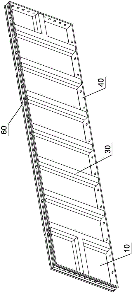
technical field [0001] The invention relates to a formwork for reinforced concrete buildings, in particular to a general formwork for pull-tab pull rods. In addition, the present invention also relates to a template system. Background technique [0002] Reinforced concrete building pouring concrete construction needs to use building formwork for forming. At present, the formwork is divided into two types of formwork, the pull-sheet system and the tie-rod system. Such as Figure 1 ~ Figure 3 Shown is the formwork of the pull-tab system, which includes a panel 10, side ribs 40, several ribs 30 are provided between the side ribs 40, and a pull-tab groove 60 is provided on the side ribs 40. When it is applied to the formwork system, it adopts The thin steel sheet passes through the pull-tab groove 60 between the two templates as a pull-tab to fasten the pull-tab. Such as Figure 4 ~ Figure 6 Shown is the formwork of the tie rod system, which includes a panel 10, reinforcing r...

Claims


Application Information

Patent Timeline
Patent Type & Authority Applications(China)
IPC IPC(8): E04G9/02E04G17/00E04G17/06
CPCE04G9/02E04G17/00E04G17/06E04G2009/028E04G2017/0646
Inventor 杨建中吴君
Owner SHENZHEN RILI TECH CO LTD
Learn More