
HRG (Hemispherical Resonator Gyros) space spherical surface sphere core aligning device and aligning method

A technology of hemispherical resonant gyroscope and alignment device, which is applied in the direction of measuring device, gyroscope effect for speed measurement, gyroscope/steering sensing equipment, etc. It can solve large alignment deviation, it is difficult to ensure that the laser passes through the spherical center of space, Affect the accuracy of the hemispherical resonant gyro and other issues to achieve high-precision alignment

Active Publication Date: 2017-03-08
CHINA ELECTRONICS TECH GRP NO 26 RES INST
View PDF5 Cites 8 Cited by
  • Summary
  • Abstract
  • Description
  • Claims
  • Application Information

AI Technical Summary

Problems solved by technology

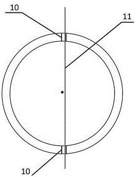
[0006] However, on the one hand, due to the limitation of precision in machining, it is difficult to make the two holes 10 on the same diameter of the spherical surface at the same time; , it is also difficult to ensure that the laser passes through the spherical center of the space without deviation, such as figure 1 shown
Therefore, the existing alignment method is difficult to achieve high-precision spatial spherical center-laser center alignment, there is a large alignment deviation, and the electrode position deviation is as high as 1.3±0.4 degrees, which will directly affect the accuracy of the hemispherical resonant gyroscope

Method used


Image

  • HRG (Hemispherical Resonator Gyros) space spherical surface sphere core aligning device and aligning method
  • HRG (Hemispherical Resonator Gyros) space spherical surface sphere core aligning device and aligning method
  • HRG (Hemispherical Resonator Gyros) space spherical surface sphere core aligning device and aligning method

Examples


Embodiment Construction

[0024] The present invention will be described in detail below in conjunction with the accompanying drawings and specific embodiments.

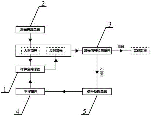
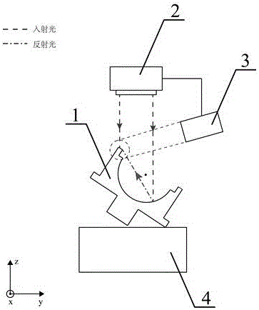
[0025] Such as figure 2 , image 3 and Figure 4 As shown, the hemispherical resonator gyroscope space spherical center alignment device of the present invention is used to align the center of the spherical surface 1 of the sample with the laser center of the laser light source unit 2 . The alignment device of the present invention includes a laser light source unit 2, which is used to generate a stable linear laser, and the laser center is on the linear laser, so that the linear laser irradiates the spherical surface 1 of the sample; Whether the incident linear laser light on the spherical surface 1 of the sample overlaps with the reflected linear laser light reflected by the spherical surface 1 of the sample; Translating the sample spherical surface 1 to) to adjust the relative position between the spherical center of the sample spheric...


PUM


Abstract

The invention discloses a HRG (Hemispherical Resonator Gyros) space spherical surface sphere core aligning device and aligning method. The aligning device comprises a laser light source unit, a laser signal detection unit and a transverse moving unit, wherein the laser light source unit is used for generating stable linear laser and irradiating the laser on the spherical surface of a sample element; the laser signal detection unit is used for recognizing whether the incident linear laser irradiated on the spherical surface of the sample element and the reflecting linear laser obtained through the spherical surface reflection are overlapped or not; the transverse moving unit is used for installing the spherical surface of the sample element and transversely moving the spherical surface of the sample element in a direction vertical to the incident linear laser so as to regulate the relative position of the spherical surface of the sample element and the laser light source unit. The laser spherical surface reflection aligning method is used; the relaying on holes obtained through mechanical processing is not needed; the high-precision space spherical surface sphere core-laser center alignment can be realized; the final electrode position deviation is modified through 1.3+ / -0.4 degrees to 0.0+ / -0.2 degrees.

Description

technical field [0001] The invention belongs to the field of hemispherical resonant gyroscopes, in particular to a hemispherical resonant gyroscope excitation cover and a base space spherical center alignment device and alignment method in a satellite strapdown inertial navigation system. Background technique [0002] Hemispherical Resonator Gyros (HRG for short) is a new type of high-precision inertial navigation gyro with great development prospects. It has long life, good stability, high reliability, low noise, low power consumption, radiation resistance, It has the characteristics of short start-up time, no wear, high impact resistance and good long-term stability. It has received extensive attention in the fields of satellites, missiles, and directional drilling. It is considered by the international inertial technology community to be the most ideal device in various strapdown inertial systems. one. [0003] As the difficulty of space exploration continues to increase...

Claims


Application Information

Patent Timeline
IPC IPC(8): G01C19/5691G01C25/00
CPCG01C19/5691G01C25/005
Inventor 刘书海蒋春桥余波杨勇方针
Owner CHINA ELECTRONICS TECH GRP NO 26 RES INST
Learn More