
Mini distributed fiber temperature measuring calibration device and method

A distributed optical fiber and calibration device technology, applied in the direction of measuring devices, thermometers, measuring heat, etc., can solve problems such as calibration and transportation that take a long time, affect the promotion of instrument use, and affect test results, etc., to improve the calibration range , reduce the difficulty and requirements of calibration, and improve the effect of uniformity

Inactive Publication Date: 2017-03-08
THE 41ST INST OF CHINA ELECTRONICS TECH GRP
View PDF15 Cites 5 Cited by
  • Summary
  • Abstract
  • Description
  • Claims
  • Application Information

AI Technical Summary

Problems solved by technology

[0003] At present, high and low temperature thermostats or constant temperature water tanks are often used for calibration. The high and low temperature thermostats are bulky, and it is difficult to calibrate the temperature coefficient of the temperature-sensitive optical cable in the field of optical cable laying. The user can only provide the optical fiber in advance for calibration, and the steps are cumbersome. , Calibration and transportation also take a long time, affecting the promotion of the instrument and the use of users; and using a constant temperature water tank to calibrate the temperature coefficient of the temperature-sensing optical cable, because the maximum temperature of the water tank can only reach 100 ° C, and the temperature coefficient of ROTDR is not linear , using the temperature coefficient calibrated at room temperature to 100°C, there will be a large error when testing at a higher temperature (such as 100-200°C), which will affect the test results

Method used


Image

  • Mini distributed fiber temperature measuring calibration device and method
  • Mini distributed fiber temperature measuring calibration device and method
  • Mini distributed fiber temperature measuring calibration device and method

Examples


Embodiment Construction

[0038] The present invention will be further described below in conjunction with the accompanying drawings and embodiments.

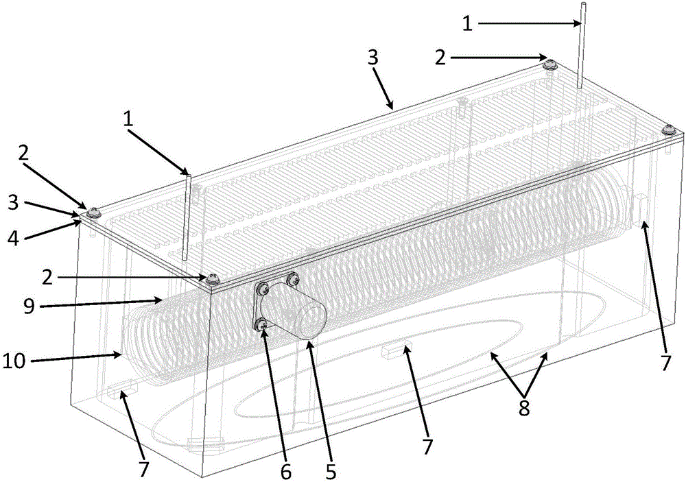
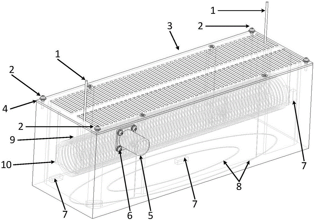
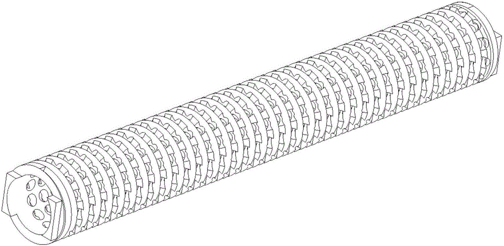
[0039] like figure 1 As shown, a miniaturized distributed optical fiber temperature measurement and calibration device includes a box, the upper panel of the box can be opened and closed, and the upper panel is provided with a through hole for the measured optical fiber 1 to pass through; The box body is provided with a detachable optical fiber winding column 9, the bottom of the box body is provided with a heating resistance wire 8, and the box body is also provided with a heat transfer fluid working medium and a temperature sensor 7, and the temperature sensor 7 and The heating resistance wires 8 are all connected with the calibration device controller.

[0040] Two micromotors 5 are also fixed on the side wall of the box, and the micromotors 5 are connected to the propellers arranged inside the box, and the micromotors 5 are also connected to the co...


PUM

PropertyMeasurementUnit
thicknessaaaaaaaaaa
lengthaaaaaaaaaa
heightaaaaaaaaaa

Abstract

The invention discloses a mini distributed fiber temperature measuring calibration device and method. The calibration device comprises a casing; an upper panel of the casing can be opened and closed, and is provided with through holes through which tested fibers can penetrate; the casing is internally provided with a detachable fiber winding column; the bottom of the casing is provided with heating resistance wires; the casing is internally provided with a heat-transfer fluid working medium and a temperature sensor; and the temperature sensor and the heating resistance wires are connected with a controller of the calibration device. A distributed temperature measuring device calibrate the fiber temperature coefficient in a miniaturized manner within the range from normal temperature to 200 DEG C, and the test device can be used to realize calibration and demonstration of a test site.

Description

technical field [0001] The invention relates to the technical field of distributed optical fiber sensor calibration, in particular to a miniaturized distributed optical fiber temperature measurement calibration device and a calibration method. Background technique [0002] In the optical fiber sensing system, the distributed optical fiber temperature measuring device (ROTDR for short) is the most mature distributed optical fiber sensor at present. It is related to the material, which is the physical parameter of the optical fiber itself, which cannot be directly tested, but can only be obtained through ROTDR indirect testing and calibration. At present, the spatial resolution index of ROTDR is mostly ≥1m. Therefore, if it is necessary to obtain the temperature coefficient of the optical fiber required by the distributed optical fiber temperature measurement device, the optical fiber with a length of more than 1m must be uniformly heated to meet the calibration requirements. ...

Claims


Application Information

Patent Timeline
Patent Type & Authority Applications(China)
IPC IPC(8): G01K15/00
CPCG01K15/005
Inventor 袁明李立功孙福德闫继送韩顺利徐玉华毕宗义刘雷代彬张平
Owner THE 41ST INST OF CHINA ELECTRONICS TECH GRP
Learn More