
Passive Correlative Imaging Optical System

A related imaging and optical system technology, applied in the direction of radio wave measurement systems, instruments, measuring devices, etc., can solve the problems of shortening the collection time of related imaging information, achieve the effect of improving imaging quality and optimizing aberration

Active Publication Date: 2020-06-30
SHANGHAI INST OF OPTICS & FINE MECHANICS CHINESE ACAD OF SCI
View PDF3 Cites 0 Cited by
  • Summary
  • Abstract
  • Description
  • Claims
  • Application Information

AI Technical Summary

Problems solved by technology

[0011] The purpose of the present invention is to provide a passive correlation imaging optical system, which collects and modulates the optical information of objects, so as to solve the problem that the traditional correlation imaging system needs laser active lighting, and improve the signal-to-noise ratio when performing correlation imaging in daytime. The information acquisition time of correlation imaging can be shortened significantly, and the correlation imaging of single exposure can be realized

Method used


Image

  • Passive Correlative Imaging Optical System
  • Passive Correlative Imaging Optical System
  • Passive Correlative Imaging Optical System

Examples


Embodiment Construction

[0039] The present invention will be further described below in conjunction with the accompanying drawings and embodiments, but the protection scope of the present invention should not be limited thereto.

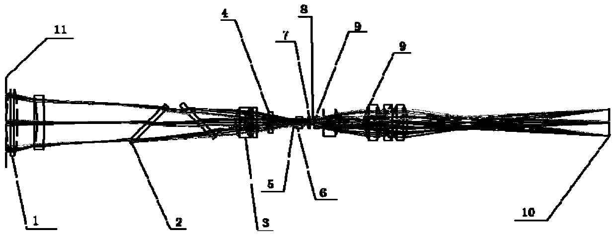
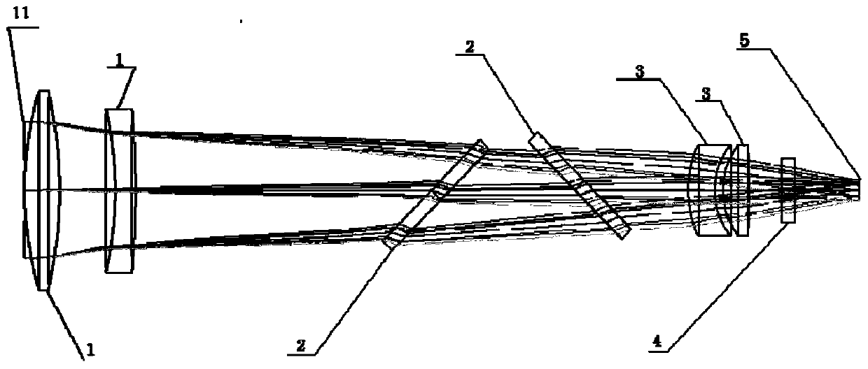
[0040] see first figure 1 , figure 1 It is an optical path diagram of an embodiment of the passive correlation imaging optical system of the present invention. As can be seen from the figure, the passive correlation imaging optical system of the present invention includes an aperture stop 11 of the front imaging mirror group, a front imaging mirror 1, a beam splitter 2, a rear imaging mirror 3, an optical filter 4, and a front imaging real image surface 5 , field lens 6, phase plate speckle modulator 7, interference speckle field 8, relay secondary imaging mirror group 9 and CCD10.

[0041] figure 2 It is an enlarged schematic diagram of the key links of the passive correlation imaging optical system. The figure shows the connection relationship between the front imaging ...


PUM


Abstract

The invention relates to a passive correlated-imaging optical system comprising four parts: a pre imaging lens group, a field lens imaging lens, a phase plate speckle modulator and a relay secondary imaging lens group. Under the circumstance of an object is irradiated by natural light, the pre imaging lens group images the object on a primary real time plane; the field lens imaging lens images an entrance pupil of the pre imaging lens group to an interference speckle field, wherein the interference speckle field is one formed behind a phase plate at a distance of 1.5mm; and then the relay secondary imaging lens group images the interference speckle field to a CCD. According to the invention, spectrum conversion is carried out on information of the spatial object; the interference speckle field is formed at the exit pupil plane, wherein information at each point on the exit pupil plane includes energy information of all object points; and then after the CCD collects the interference speckle information, the speckle field image is calculated based on an association operation and a high-spectrum object image is obtained by inversion. Therefore, a hyperspectral, three-dimensional image is obtained under single exposure.

Description

technical field [0001] The invention relates to correlation imaging, also known as ghost imaging, in particular to a passive correlation imaging optical system. Background technique [0002] Correlation imaging, also known as ghost imaging, is a new imaging technology that restores images through correlation computing methods after obtaining relevant information about objects. Compared with traditional imaging methods, it can restore object images in complex and special environments, and has broad application prospects in medicine, military, astronomy, remote sensing and other fields. [0003] In the traditional optical imaging system, the imaging system is constrained by the limited view of the detection end, while the detection and imaging in correlated imaging can be separated, so that non-local imaging can be realized. The initial correlative imaging was based on the quantum optical theory of entangled photon pairs or active illumination of pseudothermal light sources. ...

Claims


Application Information

Patent Timeline
Patent Type & Authority Patents(China)
IPC IPC(8): G01S13/89G01S7/02
CPCG01S7/02G01S13/89
Inventor 李望韩申生吴建荣沈夏龚文林陈明亮
Owner SHANGHAI INST OF OPTICS & FINE MECHANICS CHINESE ACAD OF SCI
Learn More