Airborne laser radar fixing device

A technology of airborne laser radar and fixing devices, which is applied in the directions of measuring devices, electromagnetic wave re-radiation, and utilization of re-radiation, etc., can solve problems such as damage and complex and precise internal structure, and achieve the effect of stable structure, light weight and reasonable design

Inactive Publication Date: 2017-03-08
FLIGHT AUTOMATIC CONTROL RES INST
View PDF9 Cites 2 Cited by
  • Summary
  • Abstract
  • Description
  • Claims
  • Application Information

AI Technical Summary

Problems solved by technology

This type of lidar, due to the complex and precise internal structure, is easily damaged by external vibrations and collisions.

Method used


Image

  • Airborne laser radar fixing device

Examples


Embodiment Construction

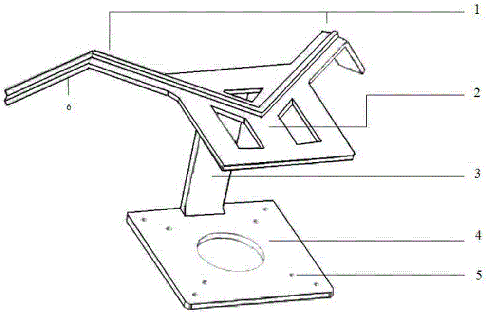
[0011] like figure 1 As shown, a specific embodiment of an airborne lidar fixing device, comprising:

[0012] 1 and 2 are the upper cover 1 and the base 2 of the laser radar fixing device respectively. Both the upper cover 1 and the base 2 are designed with large openings to reduce the overall weight of the device, and the size is larger than the laser radar cross-section, the purpose of which is to prevent aircraft collisions. Protects the lidar from impact in the event of a tip over.

[0013] 3 is a bracket connecting the upper cover 1 and the base 2, which is perpendicular to the upper cover 1 and the base 2, and its length is the height of the fixed laser radar.

[0014] 4 is a pair of extension arms on the diagonal of the upper cover plate 1 close to the bracket 3, and the ribs on the upper surface of the winglet of the device can improve the bending stiffness of the winglet, thereby improving the stability of the laser reflection measurement.

[0015] 5 is the 45° incl...


PUM


Abstract

The invention relates to a fixing device applicable to radar mounted on a small unmanned aerial vehicle, and specifically relates to an airborne laser radar fixing device. Laser radar, which is used as an environment perception unit, is equivalent to the eye of a demonstrator, and plays an important role in improving the independence ability of unmanned aerial vehicles. Laser radar is prone to damage by outside shock and collision because of a complex and precise internal structure. In order to solve the problems, the invention designs a fixing device for protecting and fixing laser radar. The device is light, stable in structure and reasonable in design, and can fix airborne laser radar effectively.

Description

technical field [0001] The invention is applicable to a fixing device for installing a radar on a small unmanned aerial vehicle, and in particular relates to an airborne laser radar fixing device. Background technique [0002] As an environmental perception unit, lidar is equivalent to the eyes of the verification machine, and plays an important role in improving the autonomy of drones. At present, the basic principle of the laser radar commonly used for small drones is that the upper part is an infrared laser transmitter, and the emission direction is vertically downward. The middle part is a rotating axicon, which reflects the vertically incident laser horizontally outward. The reflected light is reflected back to the laser rangefinder by the object, and is received by the photosensitive diode through the receiving convex lens and prism, so as to calculate the distance of the object. This type of lidar, due to the complex and precise internal structure, is easily damaged...

Claims


Application Information

Patent Timeline
Patent Type & Authority Applications(China)
IPC IPC(8): G01S17/08
CPCG01S17/08
Inventor 马蓉陈小龙顾天元马雯
Owner FLIGHT AUTOMATIC CONTROL RES INST
Why Eureka
Try Eureka