Control method of electric tool and electric tool performing same

A technology of electric tools and control methods, which is applied in the direction of adaptive control, general control system, control/regulation system, etc., and can solve the problems of troublesome manufacturing, complex structure of mechanical clutch, high cost, etc.

Active Publication Date: 2017-03-08
POSITEC POWER TOOLS (SUZHOU) CO LTD
View PDF7 Cites 11 Cited by
  • Summary
  • Abstract
  • Description
  • Claims
  • Application Information

AI Technical Summary

Problems solved by technology

However, the structure of the above-mentioned mechanical clutches is relatively complicated, the manufacture is troublesome, and the cost is relatively high.

Method used


Image

  • Control method of electric tool and electric tool performing same
  • Control method of electric tool and electric tool performing same
  • Control method of electric tool and electric tool performing same

Examples


Embodiment 1

[0060] An embodiment of the present invention provides a control method of an electric tool, such as Figure 20 As shown, the method includes the following steps:

[0061] S1, measuring the parameters used to represent the load of the output shaft that change with time, the parameters include a variety of parameters, such as current, voltage, speed, etc. The measurement method may be sampling at a fixed period.

[0062] S2. Obtain the derivative of the parameter with respect to time, specifically, it can be a first-order derivative, a second-order derivative or a higher-order derivative. This derivative is actually the slope of the curve in FIG. 1 . There are many ways to calculate the derivative, which will be described in detail below.

[0063] S3, generating a corresponding control signal based on the derivative, that is, generating the control signal according to any one of the first-order derivative, second-order derivative or higher-order derivative. These derivatives...

Embodiment 2

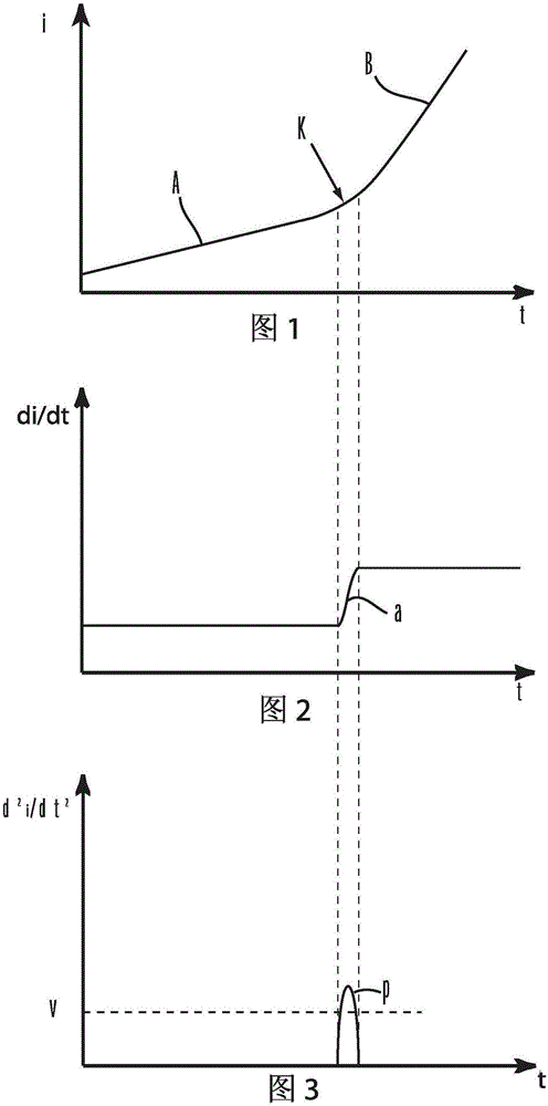
[0106] As described in the previous embodiment, Fig. 2 is the curve of the first derivative di / dt of current i versus time t in Fig. 1 picture . Among them, the first part A and the second part B in Figure 1 are in the picture The upper part is shown as a straight line parallel to the horizontal coordinate axis t, while the second part K is shown as a sharply rising curve.

[0107] Figure 3 is the second derivative d of the current i in Figure 1 with respect to time t 2 i / dt 2 after the curve picture . Among them, the values ​​of the first part A and the second part B in Fig. 1 have become zero after the second derivative, while the second part K is shown as a parabola with an opening downward, and in the top area of ​​the parabola (including the parabola A specific interval including the apex) forms a peak signal p. With reference Figure 4 As shown, when the peak signal p is formed, a control signal s will be generated accordingly. Of course, in a preferred embodimen...


PUM


Abstract

The invention relates to a control method of an electric tool. The electric tool comprises a motor and an output shaft driven by rotation of the motor. The output shaft is used for outputting a rotation torque to drive a work head to work on a work piece. The control method comprises the steps of measuring a time-varying parameter used to represent the load of the output shaft, getting a derivative of the parameter versus time, generating a corresponding control signal based on the derivative, and interrupting the torque output of the electric tool according to the control signal. According to the invention, a corresponding action is performed after the work piece is detected to reach a predetermined position, and it is guaranteed that the work piece does not pass over the predetermined position.

Description

technical field [0001] The invention relates to a control method of an electric tool. [0002] The present invention also relates to an electric tool implementing the above control method. Background technique [0003] Existing electric tools, such as electric screwdrivers, provide electric current through a loaded power supply to drive the motor to rotate, so that the working head rotates to drill the screw into the wooden board. Different types of screws have different body diameters, or different head shapes, so that they drill into the same board differently. In addition, different wood boards have different hardness due to different materials, so the situation of the same screw drilling into wood boards of different materials is not the same. Usually, during the use of an electric screwdriver, the user needs to drill the screw until the head is close to the surface of the workpiece. In this way, the user needs to pay attention to the drilling process very carefully to...

Claims


Application Information

Patent Timeline
Patent Type & Authority Applications(China)
IPC IPC(8): G05B13/04
CPCG05B13/042
Inventor 万德康张传兵
Owner POSITEC POWER TOOLS (SUZHOU) CO LTD
Why Eureka
Try Eureka