Device and method for winding a strip material

A strip and equipment technology, applied in the field of equipment and methods for coiling strip materials, can solve the problems of expensive, structural limitations, etc., and achieve the effects of simple structure, good force and moment, and high strip tension

Active Publication Date: 2017-03-08
SMS GRP GMBH
View PDF8 Cites 1 Cited by
  • Summary
  • Abstract
  • Description
  • Claims
  • Application Information

AI Technical Summary

Problems solved by technology

However, this is expensive, and thus such guides have structural limitations

Method used


Image

  • Device and method for winding a strip material
  • Device and method for winding a strip material
  • Device and method for winding a strip material

Examples


Embodiment Construction

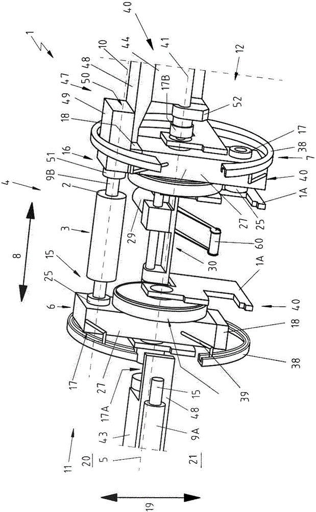
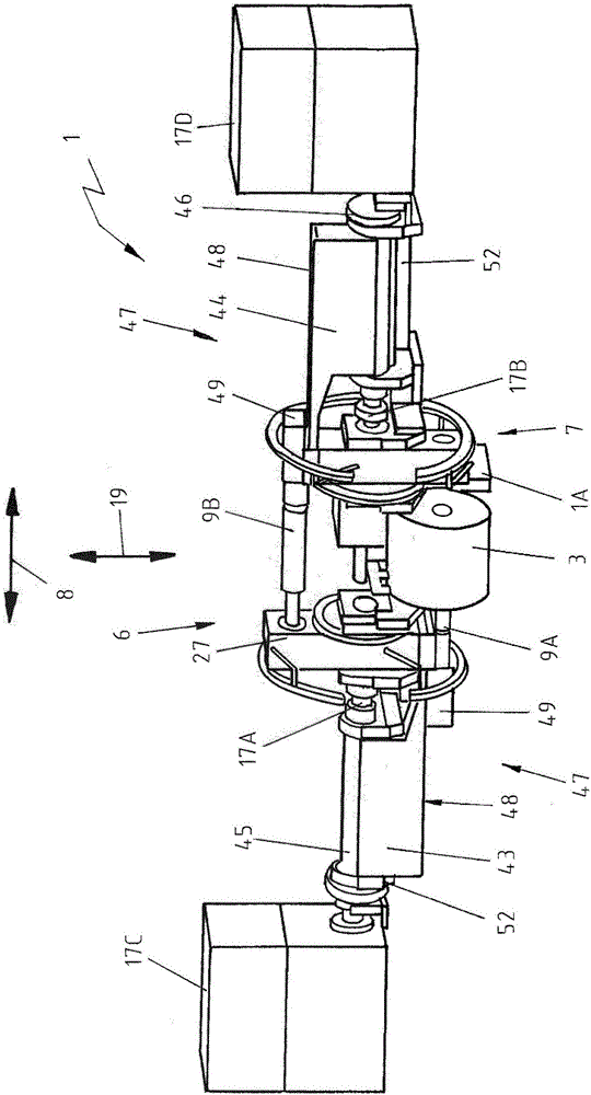
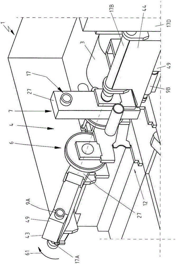
[0101] exist Figure 1 to Figure 14 A first embodiment of a device 1 for coiling a strip material 2 into a coil 3 according to the invention and its working principle are shown and described by way of example in figure 1 and figure 2 The illustration in , mainly explains the structural configuration of the device 1 in relation to the first functional relationship. Followed by Figure 3 to Figure 14 The schematic diagram of again elaborates the feasible method flow.

[0102] exist Figure 1 to Figure 14 The apparatus 1 for coiling a strip material 2 into a coil 3 shown in FIG. 2 has a rotor coiler 4 comprising two rotor side parts 6 and 7 rotatable about a common rotor axis 5 .

[0103] The rotor coiler 4 is mounted rotatably in a frame 1A of the device 1 , wherein the device 1 is fixed by means of the frame 1A on a base not shown here.

[0104] The two rotor-side parts 6 and 7 are arranged axially spaced apart from one another in the axial direction 8 of the rotor axis 5...


PUM


Abstract

The invention relates to a device (1) for winding a strip material (2) into a coil (3), comprising a rotor winder (4), which comprises two rotor lateral parts (6, 7) that can be rotated about a common rotor axis (5), which rotor lateral parts are spaced apart from each other in the axial direction (8) of the rotor axis (5) in such a way that rotationally driven winder mandrels (9) can be retained between the rotor lateral parts, wherein the device (1) comprises, outside of the rotor winder (4), two rocker parts (43, 44) that can be rocked independently of each other, which are supported in such a way that the two rocker parts can be pivoted in relation to the two rotor lateral parts (6, 7), wherein each of the rocker parts (43, 44) comprises an axial displacement apparatus (47), by means of which the winder mandrel (9A, 9B) retained on the rocker part (43, 44) can be displaced in the axial direction (8).

Description

technical field [0001] The invention relates to a plant for coiling strip material into coils, said plant having a rotor coiler comprising two rotor side parts rotatable about a common rotor axis, the rotor side parts They are arranged at a distance from one another in the axial direction of the rotor axis, ie the rotationally driven take-up mandrel can be fixed between them. [0002] The invention also relates to a method for coiling strip material into a coil with a rotor coiler rotatable about the rotor axis, wherein, for coiling the coil, the first coiling mandrel is A oscillating member first pivots into a position next to the starting winding position in the axial direction, and then moves into the starting winding position in the axial direction of the rotor axis by means of the first axial displacement device; wherein the coil In the start coiling position, the coil is wound on a first coiling mandrel fixed between the first rotor side part and the second rotor side p...

Claims


Application Information

Patent Timeline
IPC IPC(8): B21C47/24
CPCB21C47/245B65H2701/173B65H19/2215B65H19/22B21C47/24
Inventor U·帕策尔特W·邓科
Owner SMS GRP GMBH
Why Eureka
Try Eureka