Fuel gas supply system of vessel

A gas supply and fuel supply technology, applied in ship propulsion, loading system, oil supply device, etc., can solve problems such as excessive power consumption, and achieve the effects of convenient management, cost saving and manpower

Inactive Publication Date: 2017-03-08
DAEWOO SHIPBUILDING & MARINE ENG CO LTD
View PDF9 Cites 3 Cited by
  • Summary
  • Abstract
  • Description
  • Claims
  • Application Information

AI Technical Summary

Problems solved by technology

Therefore, in order to supply the boil-off gas in the cargo compartment to the MEGI engine and use the boil-off gas in the MEGI engine as fuel, it is necessary to consume excessive power to compress the boil-off gas at high pressure

Method used


Image

  • Fuel gas supply system of vessel

Examples


Embodiment Construction

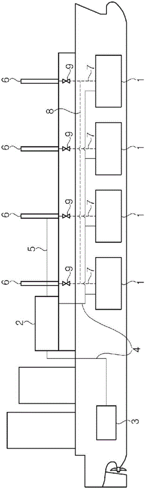
[0030] Hereinafter, configurations and effects of exemplary embodiments of the present invention will be described with reference to the accompanying drawings. In addition, the following exemplary embodiments can be changed in various forms, so the technical scope of the present invention is not limited to the following exemplary embodiments.

[0031] figure 1 is a schematic diagram of a gas supply system of a ship according to an exemplary embodiment of the present invention. Such as figure 1 As shown, the gas supply system of the ship according to the exemplary embodiment of the present invention supplies natural gas from the cargo tank 1 of the ship to the engine 3 through the fuel supply line 4 .

[0032] The ship according to the exemplary embodiment of the present invention may be any one of a liquefied natural gas carrier, a liquefied petroleum gas carrier, an ethane carrier, and a very large crude oil carrier (VLCC).

[0033] The cargo tank 1 is installed in a ship ...


PUM


Abstract

Disclosed is a fuel gas supply system (FGSS) of a vessel, which supplies natural gas to an engine as a fuel. The FGSS of the vessel includes: a storage tank in which a liquid cargo is stored; a vent mast connected to the storage tank; a fuel pipe line connected to the engine to supply the fuel; and a vent line connected to the fuel pipe line, wherein the vent line is connected to the vent mast.

Description

technical field [0001] The present invention relates to a gas supply system of a ship, and more particularly, to a gas supply system of a ship having a discharge line through which natural gas in the fuel supply line of the ship is discharged. Background technique [0002] Liquefied gases such as liquefied natural gas (LNG) and liquefied petroleum gas (LPG) are obtained by cooling natural gas or petroleum gas to cryogenic temperatures (approximately -163° C. in the case of liquefied natural gas). As a result, liquefied gas has a greatly reduced volume compared to its gaseous state, making it ideal for long-distance transportation by sea. [0003] A liquefied gas carrier, such as an LNG carrier, is used to transport the liquefied gas by sea to a ground destination and unload the liquefied gas. To this end, liquefied gas carriers include cargo compartments (commonly referred to as "cargo compartments") that can withstand the cryogenic temperatures of liquefied gas. In additi...

Claims


Application Information

Patent Timeline
Patent Type & Authority Applications(China)
IPC IPC(8): B63H21/38F02M21/02F02M37/00B63H21/12
CPCB63H21/12F02M37/00F02M21/02F02M21/0215B63H21/38Y02T10/30B63B25/14
Inventor 李准埰姜东亿朴青气
Owner DAEWOO SHIPBUILDING & MARINE ENG CO LTD
Why Eureka
Try Eureka