Iron support for chemical test

A chemical test and iron stand technology, which is applied to chemical instruments and methods, laboratory utensils, supporting utensils, etc., can solve the problems of the height adjustment and rotation adjustment of the iron stand, the inseparability of the iron stand, etc. Ease of operation and increased tightening effect

Inactive Publication Date: 2017-03-15
冯灏
View PDF8 Cites 11 Cited by
  • Summary
  • Abstract
  • Description
  • Claims
  • Application Information

AI Technical Summary

Problems solved by technology

[0006] The technical task of the present invention is to address the above deficiencies and provide an iron stand for chemical experiments to solve the problems of the existing iron stand height adjustment and rotation adjustment interacting and the iron stand being inseparable.

Method used


Image

  • Iron support for chemical test
  • Iron support for chemical test
  • Iron support for chemical test

Examples


Embodiment 1

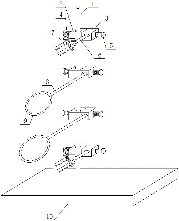
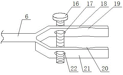
[0038] as attached figure 1 , attached figure 2 , attached image 3 And attached Figure 4 As shown, the chemical test iron frame platform of the present invention includes a base 10, a support rod 1, two test tube clamps and two iron rings, and each iron ring includes a connecting rod 8 and an outer end fixed on the connecting rod 8 Support rings 9, the diameters of the two support rings 9 are different; each test tube holder includes a rotating rod 6 and a clamping piece 7 fixed on the outer end of the rotating rod 6; the lower end of the supporting rod 1 is provided with external threads , The base 10 is provided with an installation threaded hole 11 for the support rod 1 to pass through, and the lower end of the support rod 1 is inserted into the installation threaded hole 11, that is, the support rod 1 and the base 10 are threaded. Four lifting mechanisms are arranged on the supporting rod 1, and the inner end of each connecting rod 8 and the inner end of each rotatin...

Embodiment 2

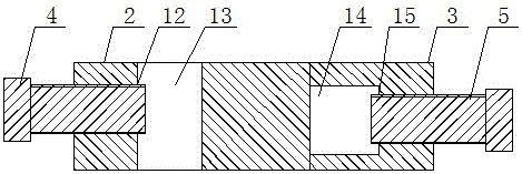
[0043] as attached Figure 5 ,. attached Figure 6 And attached Figure 7 As shown, this embodiment is a further improvement on the basis of Embodiment 1. The difference between this embodiment and Embodiment 1 is: the inner end of the fine-tuning bolt 4 is located in the fixing hole 13, and the inner end of the fine-tuning bolt 4 is fixed with a cross-section Arc-shaped support rod slot 23, the central axis of the support rod slot 23 is parallel to the central axis of the fixing hole 13, the support rod slot 23 can accommodate the support rod 1, when the fine-tuning bolt 4 is tightened to the right, the support rod The card slot 23 is inserted on the outer surface of the support rod 1, which increases the contact area between the fine-tuning bolt 4 and the support rod 1, thereby increasing the fastness of the support rod 1 in the fixing hole 13; at the same time, the positioning bolt 5 The inner end is located in the mounting hole 14, and the inner end of the positioning b...

Embodiment 3

[0046] as attached Figure 8 As shown, this embodiment is a further improvement on the basis of Embodiment 2. The difference between this embodiment and Embodiment 2 is that four support blocks 25 are fixed below the base 10, and the four support blocks 25 are distributed on the bottom of the base 10. On the four end corners; the base 10 has a receiving groove 26, the opening of the receiving groove 26 is located on the bottom surface of the base 10, and the opening of the receiving groove 26 is provided with a cover plate 27 slidably connected with it. Specifically, two guide rails are arranged on the opening of the accommodation groove 26, and the two guide rails are symmetrically fixed on the left and right sides of the opening of the accommodation groove 26, and the cover plate 27 is slidably connected on the two guide rails, the cover plate 27 and the accommodation groove 26 forms an openable or closed accommodating cavity, which can be used to place asbestos nets.


PUM


Abstract

The invention discloses an iron support for a chemical test, belongs to the field of chemical test devices and aims to solve the technical problems that height adjustment and rotation adjustment of an existing iron support are mutually affected, and the existing iron support cannot be detached. The iron support structurally comprises a base, a supporting rod, a plurality of test tube clamps and a plurality of iron rings, each iron ring comprises a connecting rod and a supporting ring fixed at the outer end of the connecting rod, the diameters of the supporting rings are different, each test tube clamp comprises a rotating rod and clamping parts fixed at the outer end of the rotating rod, the supporting rod is detachably and vertically fixed on the base, a plurality of lifting mechanisms are arranged on the supporting rod, the inner end of each connecting rod and the inner end of each rotating rod are detachably connected on the lifting mechanisms corresponding to the connecting rod and the rotating rod, and the lifting mechanisms can drive the connecting rods or the rotating rods to vertically move along the supporting rod.

Description

technical field [0001] The invention relates to the field of chemical test devices, in particular to an iron stand for chemical tests. Background technique [0002] The iron stand is used to fix and support various instruments, and the iron ring can be used instead of the funnel stand. It is generally used in experimental operations such as filtration, heating, and titration. It is one of the most widely used instruments in physics and chemistry experiments. Often used in conjunction with alcohol lamps. Note that the order is "from bottom to top". When using the iron stand, it should be placed on a horizontal desktop, and the iron clip should be clamped firmly. When the acid-base reagent drips on the iron stand, it should be washed with water immediately. [0003] During the use of the iron stand, it will face height adjustment and rotation adjustment. The height adjustment is mainly for the up and down movement of the iron ring and the test tube holder; the rotation ad...

Claims


Application Information

Patent Timeline
Patent Type & Authority Applications(China)
IPC IPC(8): B01L9/00
CPCB01L9/00B01L2200/023
Inventor 冯灏
Owner 冯灏
Why Eureka
Try Eureka