A hydraulic pulse generating device and its operating method

A pulse generating device and hydraulic technology, applied in the direction of vibration drilling, etc., can solve the problems such as the influence of the structure size of the lower drilling tool, and the technology cannot be applied universally, so as to achieve convenient operation, increase the rock breaking speed, and the device structure is simple Effect

Active Publication Date: 2018-09-07
SOUTHWEST PETROLEUM UNIV
View PDF13 Cites 0 Cited by
  • Summary
  • Abstract
  • Description
  • Claims
  • Application Information

AI Technical Summary

Problems solved by technology

Although there are many existing methods for increasing drilling speed, field data show that these technologies cannot be applied universally, and some tools even have a greater impact on the lower drilling tool due to the structural size

Method used


Image

  • A hydraulic pulse generating device and its operating method
  • A hydraulic pulse generating device and its operating method
  • A hydraulic pulse generating device and its operating method

Examples


Embodiment Construction

[0026] The present invention will be further described below in conjunction with the accompanying drawings.

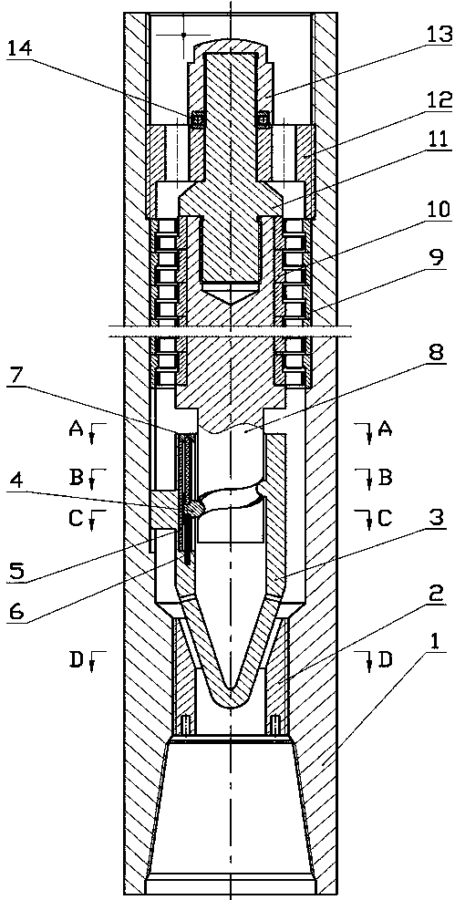
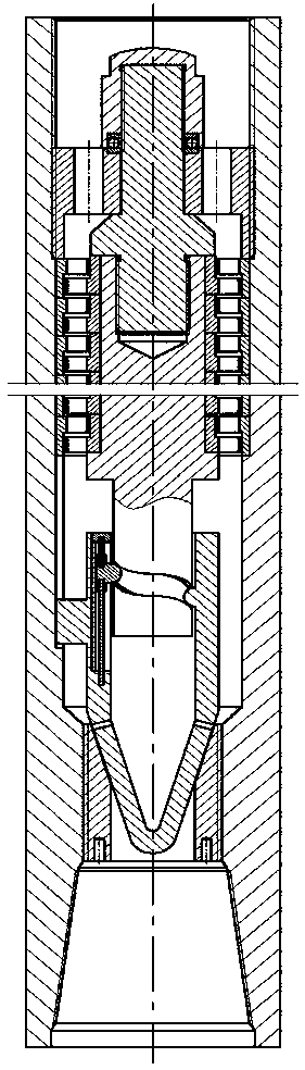
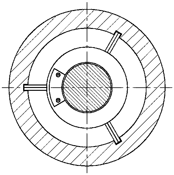
[0027] Such as Figure 1-11 As shown, a hydraulic pulse generating device is mainly composed of a housing 1, a throttle nipple 2, an elastic nipple 3, a centralizing block 4, a gasket 5, a spring 6, a spring cover 7, a transmission shaft 8, and a turbine stator 9. The turbine rotor 10, pull rod 11, support plate 12, support cap 13, and thrust bearing 14 are characterized in that: the throttle nipple 2 is connected to the lower end of the housing 1 through threads, and the throttle nipple 2 is connected to the spring The short joint 3 forms a hydraulic pulse generating unit, and the centralizing block 4 is installed in the T-shaped slot of the short joint 3. The T-shaped slot of the short joint 3 is provided with a gasket 5 and the upper and lower ends of the centralizing block 4. Both are equipped with springs 6, and the spring cover 7 is used to prevent the spring 6 ...


PUM


Abstract

The invention discloses a hydraulic pulse generating device. The hydraulic pulse generating device mainly comprises a shell, a throttling nipple, a bullet-shaped nipple, a straightening block, a spacer, springs, a spring cover, a transmission shaft, a turbine stator, a turbine rotor, a pull rod, a supporting disc, a supporting cap and a thrust bearing, and is characterized in that the throttling nipple is connected to the lower end of the shell through threads; the throttling nipple and the bullet-shaped nipple form a hydraulic pulse generating unit; the straightening block is mounted inside a T-shaped groove in the bullet-shaped nipple; the spacer is arranged inside the T-shaped groove in the bullet-shaped nipple; the springs are mounted at both the upper end and the lower end of the straightening block; the spring cover is used for preventing the spring at the upper end of the straightening block from breaking away; a closed chute is formed in the cylindrical surface of the lower end of the transmission shaft; the turbine stator and the turbine rotor form a power unit; the turbine stator and the turbine rotor are fixed to the shell and the transmission shaft in a tightly pressing manner respectively; the pull rod, the supporting disc, the supporting cap and the thrust bearing form a supporting unit together. The hydraulic pulse generating device is simple in structure and convenient to operate and has easily adjustable shock frequency.

Description

technical field [0001] The invention relates to a hydraulic pulse generating device and an operating method thereof, belonging to the technical field of drilling engineering in the oil and gas exploitation industry. Background technique [0002] The oil and gas resources in the stratum are produced based on certain drilling and production techniques, through the drilling system to form well holes in the stratum, and the system includes surface systems and downhole equipment. Among them, the drill string is one of the most important downhole equipment. It serves not only as a bridge to transmit wellhead power, but also as a barrier to isolate the inner and outer annular drilling fluids. With the continuous exploitation of oil and gas resources, drilling operations are continuously shifted to deep formations, and the number of deep and ultra-deep wells is gradually increasing. According to the distribution characteristics of my country's oil and gas resources, 52% of the natu...

Claims


Application Information

Patent Timeline
Patent Type & Authority Patents(China)
IPC IPC(8): E21B7/24
CPCE21B7/24
Inventor 汤历平黄泽民祝效华
Owner SOUTHWEST PETROLEUM UNIV
Why Eureka
Try Eureka