
Method and system to operate a compressor for an engine

An engine system and compressor technology, applied in combustion engine, engine control, engine components, etc., can solve the problems of turbocharger not providing engine airflow, non-recovery, energy loss, etc., to improve engine air-fuel control, fast speed The effect of using boost pressure

Active Publication Date: 2017-03-15
FORD GLOBAL TECH LLC
View PDF4 Cites 1 Cited by
  • Summary
  • Abstract
  • Description
  • Claims
  • Application Information

AI Technical Summary

Problems solved by technology

However, when the compressor bypass valve is opened, the energy applied to the pressurized air is lost and this energy is not recoverable
Also, if the driver applies the accelerator pedal after the air pressure downstream of the compressor drops, the turbocharger may not be able to provide the desired engine airflow

Method used


Image

  • Method and system to operate a compressor for an engine
  • Method and system to operate a compressor for an engine
  • Method and system to operate a compressor for an engine

Examples


Embodiment Construction

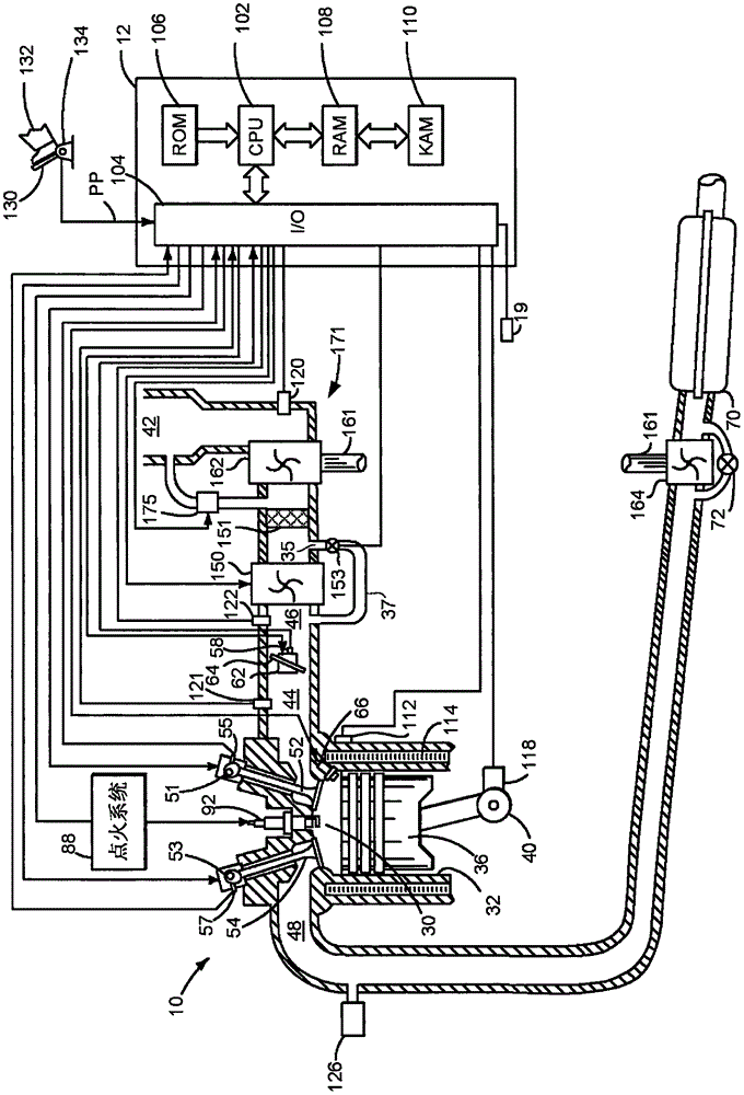
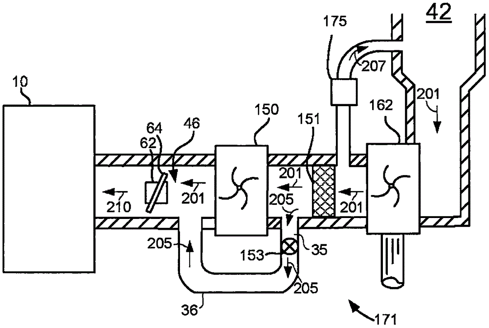
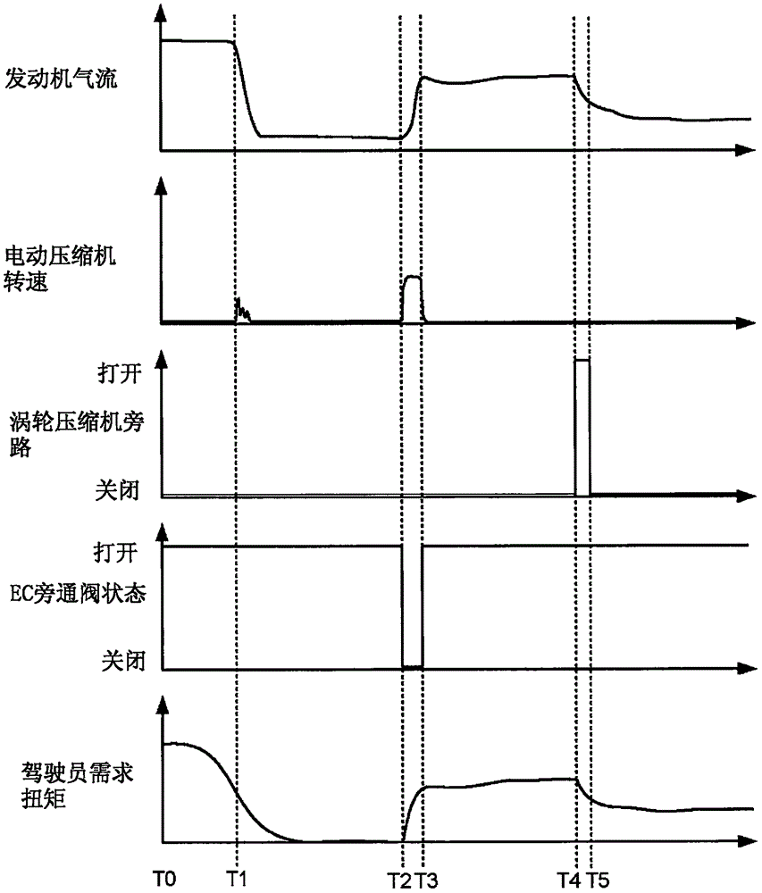
[0011] This instruction relates to the operation of an engine including a turbocharger compressor. A turbocharger compressor may experience oscillations in rotational speed if it is exposed to certain pressure ratios or flow conditions. figure 1 An example engine including two compressors is shown. Pressure oscillations in the engine air intake can be manipulated by figure 2 The electric drive compressor in the arrangement shown is lowered. image 3 An example engine operating sequence for controlling pressure and flow in an engine air intake is shown. Figure 4 A method for operating an engine and reducing the likelihood of compressor surge is shown.

[0012] refer to figure 1 , an internal combustion engine 10 comprising a plurality of cylinders, one cylinder at figure 1 is shown in . Engine 10 includes combustion chamber 30 and cylinder walls 32 with piston 36 positioned therein and connected to crankshaft 40 . Combustion chamber 30 is shown communicating with intak...


PUM


Abstract

Methods and systems for operating an engine that includes two compressors are disclosed. In one example, an electrically driven compressor is activated in response to conditions where a turbocharger compressor speed oscillates. The electrically driven compressor is activated to cancel engine air intake flow oscillations that may be caused by the turbocharger compressor.

Description

Background technique [0001] A turbocharger compresses the air supplied to the engine to improve engine performance. The speed of the turbocharger can be controlled via a wastegate. The wastegate may be selectively opened and closed to regulate compressor speed. Nonetheless, a turbocharger compressor may oscillate if there is a large change in flow through the compressor. For example, if the driver at least partially releases the accelerator pedal from a higher driver demand to a lower driver demand, the compressor may begin to oscillate. Closing the throttle quickly can cause the air flow through the compressor to decrease, causing the compressor to start oscillating. One way to reduce the possibility of compressor oscillation is to install a compressor bypass valve, which allows air to return from the outlet of the compressor to the inlet of the compressor. However, when the compressor bypass valve is opened, the energy applied to the pressurized air is lost and this ener...

Claims


Application Information

Patent Timeline
Patent Type & Authority Applications(China)
IPC IPC(8): F02B37/12F02B37/04F02B37/18
CPCF02B37/04F02B37/12F02B37/18F02B2037/122F02B37/14F02B39/10F02D41/0005F02D41/0007Y02T10/12Y02T10/40
Inventor 肖柏韬H-R·奥斯莎拉A·N·班克
Owner FORD GLOBAL TECH LLC
Learn More