A kind of exhaust device for direct air cooling unit

An air-cooling unit and steam exhaust technology, which is applied to steam/steam condensers, lighting and heating equipment, etc., can solve the problems of increasing the construction and operation costs of direct air-cooling units, large overall engineering volume, and high construction costs to meet the requirements of condensing steam Technical requirements, good economy, and the effect of reducing the amount of construction work

Active Publication Date: 2019-05-17
DONGFANG TURBINE CO LTD
View PDF8 Cites 0 Cited by
  • Summary
  • Abstract
  • Description
  • Claims
  • Application Information

AI Technical Summary

Problems solved by technology

Although these existing peak condensing technologies can help the air-cooled island reduce the exhaust back pressure of the direct air-cooled unit, they need to lay additional pipelines and build foundations. Construction and operating costs, poor economy

Method used


Image

  • A kind of exhaust device for direct air cooling unit
  • A kind of exhaust device for direct air cooling unit

Examples


Embodiment 1

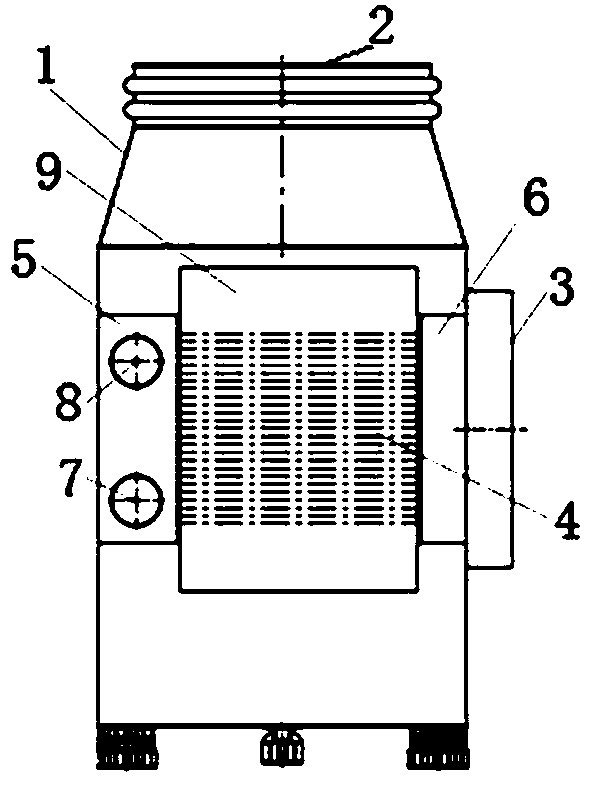
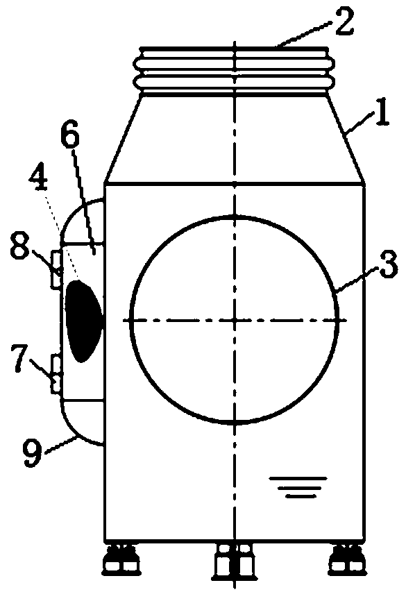
[0013] see figure 1 and figure 2 As shown, the present invention is an exhaust device for a direct air-cooling unit, which includes an exhaust device body and an indirect wet-condensing condenser (hereinafter referred to as a wet-condensing condenser).

[0014] Wherein, the exhaust device body is mainly composed of an exhaust casing 1, an exhaust inlet 2, an exhaust outlet 3, a hot well and a support arranged on the exhaust casing 1. The exhaust steam inlet 2 is located on the top of the exhaust steam housing 1 . The exhaust steam outlet 3 is located on the side wall of the exhaust steam casing 1 below the exhaust steam inlet 2 . There is also a steam condensation window on the side wall of the exhaust casing 1 below the exhaust inlet 2, and the condensation window and the exhaust outlet 3 are located on the adjacent side wall of the exhaust casing 1, and are also located Between the steam path stroke of the steam inlet 2 and the steam exhaust outlet 3, the radial angle be...

Embodiment 2

[0018] The invention relates to a steam exhaust device for a direct air cooling unit, which comprises a steam exhaust device body and a wet cooling condenser.

[0019] Among them, the main body of the exhaust device is mainly composed of an exhaust shell, an exhaust inlet, an exhaust outlet, a hot well and a support arranged on the exhaust shell. The exhaust steam inlet is at the top of the exhaust casing. The exhaust steam outlet is located on the side wall of the exhaust steam casing below the exhaust steam inlet. There is also a steam condensation window on the side wall of the exhaust shell below the exhaust steam inlet. The steam condensation window and the exhaust steam outlet are located on the adjacent side wall of the exhaust Between the steam passage strokes of the steam outlet, the radial angle between the centerline of the condensation window and the centerline of the exhaust outlet in the exhaust casing is less than 180°, preferably 90°.

[0020] The wet cooling...


PUM


Abstract

The invention discloses a steam exhaust device for a direct air-cooling unit. The steam exhaust device is provided with a wet-condensing condenser, and the steam side of the wet-condensing condenser communicates with the steam passage of the steam exhaust device. On the premise of not affecting its original function, the present invention increases the condensation function by adding a wet condenser inside it, and forms an exhaust device with a built-in peak condenser. When the exhaust device is applied to a direct air-cooled unit, It can not only realize peak condensation and meet the technical requirements of condensation, but also does not need to build a peak condensation exhaust branch, and does not need to build a separate peak condenser, which is conducive to the simplification and integration of the exhaust structure of the direct air cooling unit. The compact layout is conducive to greatly reducing the construction quantity of the direct air-cooling unit, reducing the difficulty of construction, and reducing the construction cost. It has good economy, high reliability and strong practicability.

Description

technical field [0001] The invention relates to a steam exhaust device for a direct air cooling unit. Background technique [0002] The exhaust device is a device arranged between the low-pressure cylinder of the direct air-cooled steam turbine and the exhaust pipe. It has the functions of exhaust channel, condensed water deoxygenation, condensed water collection, drainage and expansion, but has no condensing function. The condensation of the direct air-cooled unit is realized through the air-cooled island downstream of the exhaust pipe; since the condensation of the direct air-cooled unit is greatly affected by environmental changes, it is easy to cause the unit to be recirculated due to hot wind in hot weather and strong wind in summer. The exhaust pressure of the direct air-cooled unit rises in a straight line - that is, the summer back pressure of the direct air-cooled unit is relatively high, and it is difficult for a single air-cooled island to meet the four-season con...

Claims


Application Information

Patent Timeline
Patent Type & Authority Patents(China)
IPC IPC(8): F28B9/00
CPCF28B9/00
Inventor 颜强马平杰马小杰杨必林杜立刚周进米沛游克华高晓亮姬艳云郑雯
Owner DONGFANG TURBINE CO LTD
Why Eureka
Try Eureka