Double-wedge centering assembly and adjustment method

An adjustment method and double optical wedge technology, applied in installation, optics, optical components, etc., can solve the problem of inability to correct the position of the optical wedge and the lens barrel, and achieve the effect of controllable process

Active Publication Date: 2017-03-15
LUOYANG INST OF ELECTRO OPTICAL EQUIP OF AVIC
View PDF7 Cites 16 Cited by
  • Summary
  • Abstract
  • Description
  • Claims
  • Application Information

AI Technical Summary

Problems solved by technology

However, due to the error in the processing of the double-wedge lens barrel, it is necessary to adjust the position between the optical wedge and the lens barrel when the paired double-wedge is selected and loaded into the lens barrel. The current calibration method can only correct the position of the double-wedge, but cannot correct it. Wedge and Tube Positions

Method used


Image

  • Double-wedge centering assembly and adjustment method
  • Double-wedge centering assembly and adjustment method
  • Double-wedge centering assembly and adjustment method

Examples


Embodiment Construction

[0019] Embodiments of the present invention are described in detail below, and the embodiments are exemplary and intended to explain the present invention, but should not be construed as limiting the present invention.

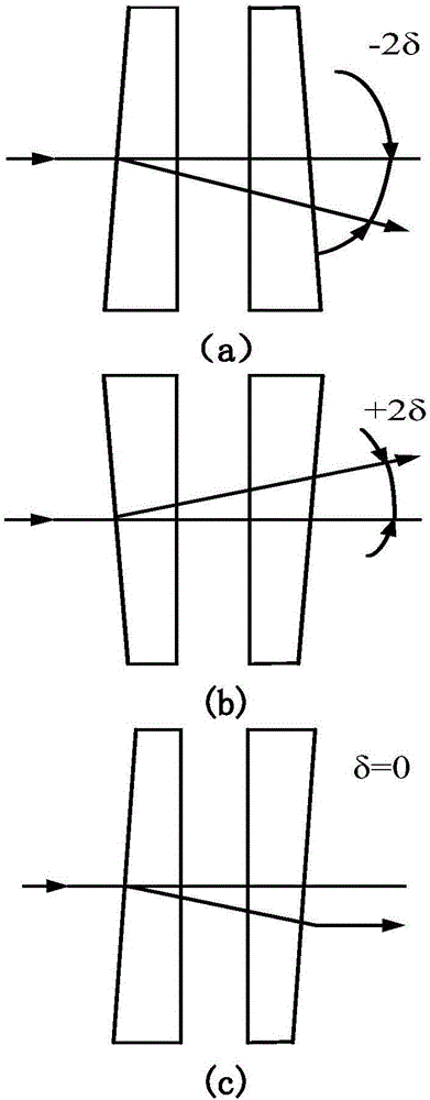
[0020] The optical wedge is an optical component used to change the direction of the outgoing light in the infrared imaging optical system. By rotating the double optical wedge and controlling the relative angle of the two optical wedges, the position of the optical axis can be changed to achieve fast and large-scale scanning of the field of view on the object side.

[0021] There is an air gap between the two optical wedges, so that the adjacent working surfaces are parallel and can rotate relatively around their common normal. Theoretically, when the main sections of the two optical wedges coincide and the two wedge angles face one side, the maximum total deflection angle (for The sum of the deflection angles produced by the two optical wedges), when the rela...


PUM


Abstract

The invention puts forward a double-wedge centering assembly and adjustment method. A transmission type center deviation measurement method is adopted. When the deflection angle is zero, the double wedges are equivalent to a parallel plate, and the center deviation of incident parallel light after the light passes through the double wedges is zero. The double wedges are rotated to determine the zero position, the zero position is bonded and fixed, and the positions of the double wedges are detected by use of the method after curing. By using the double-wedge centering assembly and adjustment method put forward by the invention, the double-wedge assembly and adjustment process is controllable and adjustable, and it is ensured that the optical axis can be set to zero after double-wedge assembly and adjustment.

Description

technical field [0001] The invention belongs to the technical field of optical machine assembly and adjustment, in particular to a double optical wedge centering assembly method. Background technique [0002] The optical wedge is an optical component used to change the direction of the outgoing light in the infrared imaging optical system. By rotating the double optical wedge and controlling the relative angle of the two optical wedges, the position of the optical axis can be changed to achieve fast and large-scale scanning of the field of view on the object side. [0003] The optical axis correction method of double wedge can be divided into two kinds: manual correction and automatic correction. The manual correction method is based on the engraved line on the optical wedge lens barrel to control the rotation of the double optical wedge. The scale value corresponding to the wedge; the automatic correction method is based on the stepping motor instead of manual rotation of t...

Claims


Application Information

Patent Timeline
Patent Type & Authority Applications(China)
IPC IPC(8): G02B7/18
CPCG02B7/1805
Inventor 谈蕊王旭朝赵建辉谢文芳
Owner LUOYANG INST OF ELECTRO OPTICAL EQUIP OF AVIC
Why Eureka
Try Eureka