Control method for preventing submersible linear motor from bumping

A technology of linear motor and control method, applied in the direction of AC motor control, control system, electrical components, etc., can solve the problems of frequent failures and low reliability, and achieve the effect of small efficiency loss, avoidance of mover collision, and easy implementation.

Active Publication Date: 2017-03-15
NO 719 RES INST CHINA SHIPBUILDING IND
View PDF4 Cites 2 Cited by
  • Summary
  • Abstract
  • Description
  • Claims
  • Application Information

AI Technical Summary

Problems solved by technology

[0004] Submersible linear motors have been tried in various oil

Method used


Image

  • Control method for preventing submersible linear motor from bumping
  • Control method for preventing submersible linear motor from bumping
  • Control method for preventing submersible linear motor from bumping

Examples


Embodiment Construction

[0037] The present invention will be described in detail below with reference to the accompanying drawings and the embodiments thereof, but the protection scope of the present invention is not limited to the scope described in the embodiments.

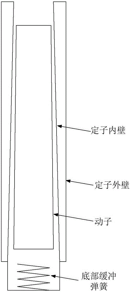
[0038] figure 1 It is a schematic structural diagram of the submersible linear motor adopted in the present invention. The submersible linear motor is a cylindrical synchronous motor, the stator coil of the linear motor is sealed in the outer cylinder, and the cylindrical mover composed of permanent magnets is surrounded by the outer cylinder. After the control cabinet inputs three-phase AC voltage to the stator of the motor, a traveling wave magnetic field will be generated in the stator, which can drive the mover to reciprocate up / down. In order to prevent the mover from going up or down from the stator, there are limit devices at the upper and lower ends of the motor stator. The limit device at the lower part of the motor adopts a...


PUM


Abstract

The invention discloses a control method for preventing a submersible linear motor from bumping. The submersible linear motor comprises a stator and a mover, wherein the stator is provided with an upper limit device and a lower limit device, the mover does reciprocating motion between the upper limit device and the lower limit device, and a motion period and a waiting period are alternately carried out in a motion process. The method is characterized by comprising steps that the displacement information is acquired on the basis of a voltage of the submersible linear motor, and a driving voltage of a driving motor is changed on the basis of the displacement information. The method is advantaged in that jig frequency stepless adjustment on the submersible linear motor can be realized, electricity consumption for keeping the position of the mover generally does not increase, and thereby jig frequency stepless adjustment is realized on the condition that the position of the mover is kept unchanged.

Description

technical field [0001] The invention belongs to the field of oil exploitation equipment, and in particular relates to a control method for avoiding frequent collisions of movers of submersible linear motors and realizing stepless adjustment of stroke times. Background technique [0002] Beam pumping units are generally used in oil fields. This oil extraction method converts the rotational motion of the pulley into the up and down reciprocating motion of the sucker rod through mechanical transmission. Therefore, the structure is simple and the reliability is high, but there is also a large loss of efficiency in the transmission link. , pipe rod eccentric wear and large noise and other deficiencies. [0003] The pumping unit using the submersible reciprocating linear motor is driven by a cylindrical linear motor. The stator coil of the motor is sealed in the outer cylinder. The inner cylinder is a mover composed of permanent magnets. Three-phase AC voltage is input to the stat...

Claims


Application Information

Patent Timeline
IPC IPC(8): H02P25/032H02P25/06
CPCH02P25/06
Inventor 欧阳晖刘尚伟吴浩伟蔡凯徐正喜魏华陈涛方芸雷阳杜红彪杨辉马坤
Owner NO 719 RES INST CHINA SHIPBUILDING IND
Why Eureka
Try Eureka