FPGA-based image compression method and apparatus, and FPGA-based image transmission system

A technology of image compression and image data, which is applied in the field of image processing, can solve the problem that image data cannot be transmitted in real time without loss, and achieve the effect of improving compression rate, ensuring image quality, and ensuring quality

Inactive Publication Date: 2017-03-15
TIANJIN JINXIN MICROELECTRONICS TECH CO LTD
View PDF5 Cites 6 Cited by
  • Summary
  • Abstract
  • Description
  • Claims
  • Application Information

AI Technical Summary

Problems solved by technology

[0005] In view of this, the object of the present invention is to provide a method, device and transmission system based on FPG

Method used


Image

  • FPGA-based image compression method and apparatus, and FPGA-based image transmission system
  • FPGA-based image compression method and apparatus, and FPGA-based image transmission system
  • FPGA-based image compression method and apparatus, and FPGA-based image transmission system

Examples


Embodiment 1

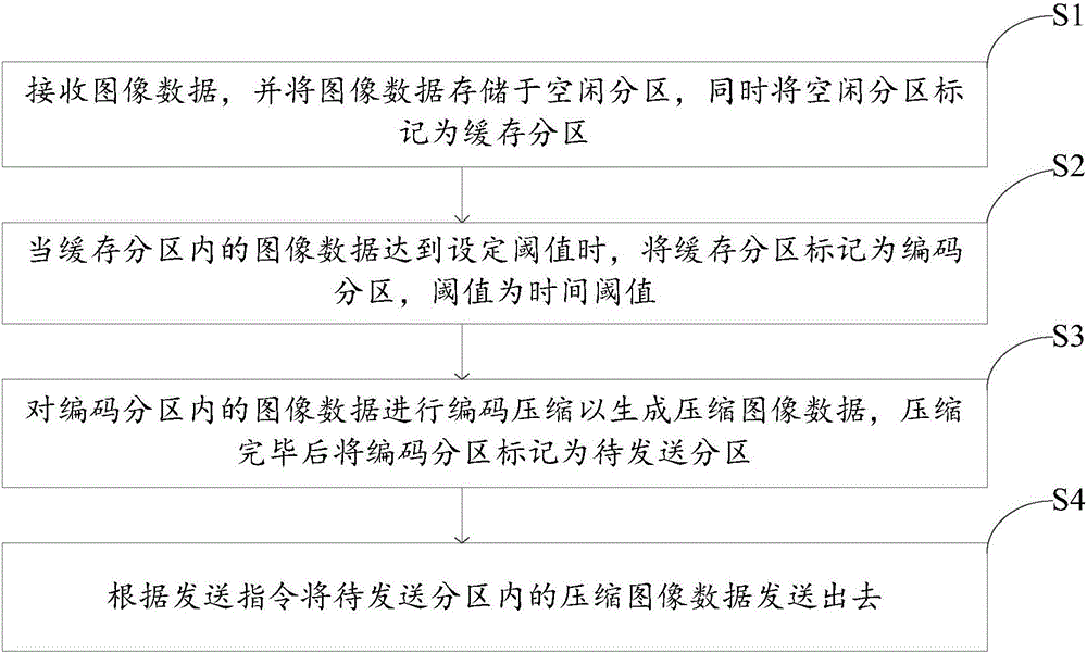
[0042] Such as figure 1 As shown, the embodiment of the present invention provides a kind of FPGA-based image compression method, comprises the following steps:

[0043] S1. Receive image data, store the image data in a free partition, and mark the free partition as a cache partition.

[0044] The image data in this embodiment is the PCB board image data collected by the CCD, and the new image data can only transmit the image data to the free partition, that is, for the single-channel image data, the image data is divided into blocks when the buffer area reaches the set threshold , and the cache area is marked as an encoding partition. At this time, the new data block cannot transmit image data to other partitions other than the free partition, but can only transmit image data to one of the free partitions.

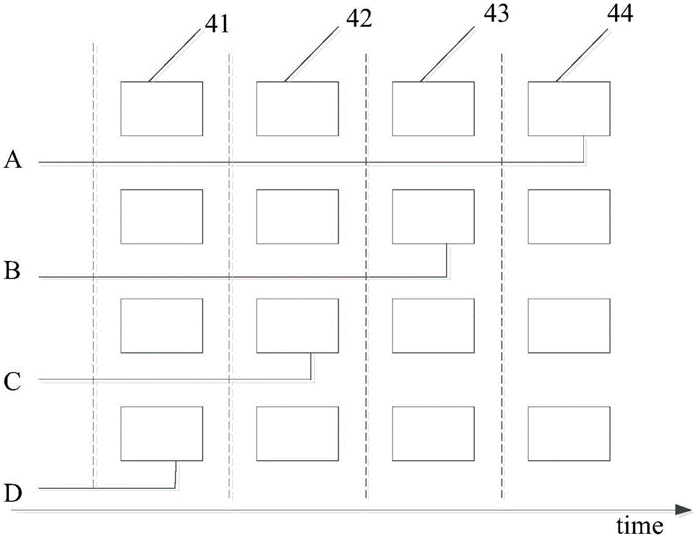
[0045] Such as figure 2 As shown, on the time axis, according to the usage of each partition, it is divided into a free partition 41, a buffer partition 42, a coding p...

Embodiment 2

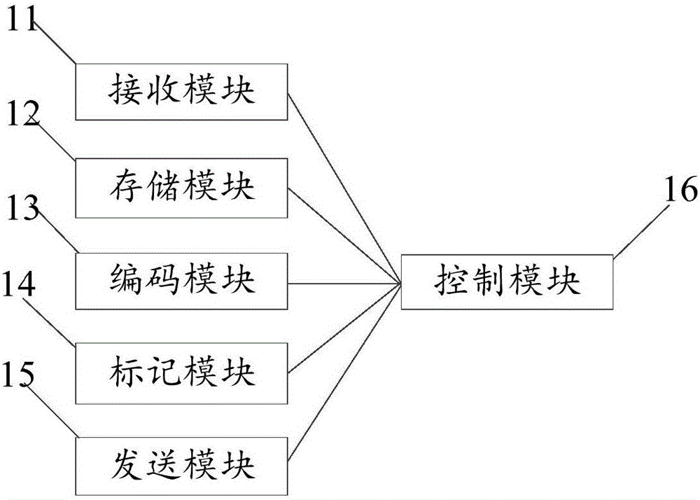
[0054] Such as image 3 As shown, the embodiment of the present invention provides a FPGA-based image compression device, including a receiving module 11, a storage module 12, an encoding module 13, a marking module 14, a sending module 15 and a control module 16;

[0055] The storage module 12 includes several partitions, including at least idle partitions according to the state of use;

[0056] The image data received by the receiving module 11 is stored in the free partition, and is marked as a cache partition by the marking module 14;

[0057] When the data in the cache partition reaches the set threshold, it is marked as an encoding partition by the marking module 14, and simultaneously sends a first state marking signal to the control module 16, and the threshold is a time threshold;

[0058] The control module 16 receives the first state marking signal, and controls the encoding module 13 to encode and compress the image data in the encoding subregion to generate image...

Embodiment 3

[0067] Such as Figure 4 Described, the embodiment of the present invention provides based on FPGA image transmission system, comprises CCD2, upper computer 3 and image compression device 1 as described in embodiment 2, receiving module 11 is used for receiving the image data that CCD 2 gathers, and image compression device 1. Send the compressed image data in the area to be sent to the host computer 3.

[0068] The image compression device 1 receives the image data collected by the CCD 2, caches and compresses the image data, and then sends the compressed image data to the host computer 3, realizing the real-time transmission of the image data.

[0069] In this embodiment, the upper computer 3 includes a decompression module, and the decompression module is used to decompress the compressed image data, so as to obtain the lossless data of the PCB board.


PUM


Abstract

The invention provides an FPGA-based image compression method and apparatus, and an FPGA-based image transmission system, and relates to the technical field of image processing. The FPGA-based image compression method comprises the following steps: receiving image data, and storing the image data in an idle subarea, and meanwhile marking the idle subarea as a cache subarea; when the image data in the cache subarea reach a set threshold, marking the cache subarea as an encoding subarea; performing encoding compression on the image data in the encoding subarea to generate image compression data, and marking the encoding subarea as a to-be-sent subarea; and sending the image compression data in the to-be-sent subarea according to a sending instruction. The existing technical problem that real-time lossless transmission of the image data cannot be realized is solved, and a technical effect of real-time lossless transmission of the image data is realized.

Description

technical field [0001] The invention relates to the technical field of image processing, in particular to an FPGA-based image compression method, device and transmission system. Background technique [0002] Photolithography is the technique used to print a pattern of features on the surface of a substrate. Such substrates can be used in the manufacture of semiconductor devices, various integrated circuits, flat panel displays (such as liquid crystal displays), circuit boards, biochips, micromechanical electronic chips, optoelectronic circuit chips, and the like. [0003] In the lithography system of the direct-write lithography machine, the feature pattern is generated by the micromirror array of the spatial light modulator. These tiny mirrors can be independently addressed and individually controlled to reflect the irradiated beam in different oblique directions to produce spatial light intensity. Finally, the characteristic graphics are projected onto the printed circuit...

Claims


Application Information

Patent Timeline
IPC IPC(8): H04N19/42H04N19/423H04N7/18
CPCH04N19/42H04N7/18H04N19/423
Inventor 施楠
Owner TIANJIN JINXIN MICROELECTRONICS TECH CO LTD
Why Eureka
Try Eureka