
Self-centering multi-claw chuck device

A claw chuck and self-centering technology, which is applied in the field of self-centering multi-jaw chuck devices, can solve problems such as the inability to guarantee the coaxiality of the inner holes at both ends of special-shaped workpieces, the inability to process special-shaped workpieces, and difficult processing operations. To achieve the effect of ensuring the final machining accuracy, good clamping effect and low production cost

Inactive Publication Date: 2017-03-22
48TH RES INST OF CHINA ELECTRONICS TECH GROUP CORP
View PDF12 Cites 7 Cited by
  • Summary
  • Abstract
  • Description
  • Claims
  • Application Information

AI Technical Summary

Problems solved by technology

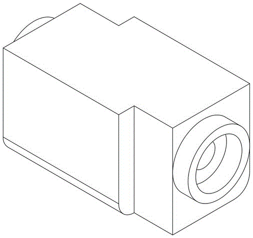
[0003] but if figure 1 As shown, when the shape of some workpieces is not cylindrical, but square or other complex shapes, and the processing of these special-shaped workpieces also requires the inner holes and outer circles at both ends to be coaxial, there will be difficulties in processing
Because although the three-jaw chuck has the function of centering, it can only clamp circular parts. If it clamps special-shaped workpieces, it cannot guarantee the coaxiality of the inner holes at both ends of the special-shaped workpieces.
However, if the double-top form is used, the inner hole of the special-shaped workpiece cannot be processed.
If you use other equipment (such as a five-axis machining center), the cost is more expensive and the processing is difficult

Method used


Image

  • Self-centering multi-claw chuck device
  • Self-centering multi-claw chuck device
  • Self-centering multi-claw chuck device

Examples


Embodiment Construction

[0028] The present invention will be described in further detail below in conjunction with specific embodiments and accompanying drawings.

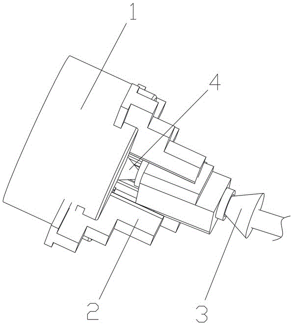
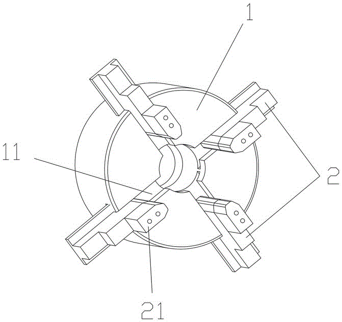
[0029] Such as Figure 1 to Figure 7 As shown, the present invention provides a self-centering multi-jaw chuck device, which is used to cooperate with a processing machine tool after clamping a workpiece so that the processing machine tool can process the clamped workpiece. The self-centering multi-jaw chuck device includes a chuck base 1, on which a plurality of jaws 2 are arranged in a circumferential manner, and a plurality of jaws 2 are enclosed to form a fixed cavity for placing workpieces. The claws 2 can move back and forth independently along the radial direction of the chuck base 1 for clamping the workpiece in the fixed cavity. The centering top assembly 4, the central axis of the centering top assembly 4 coincides with the central axis of the tailstock top 3. During operation, the tailstock top 3 and the centering top assembly...


PUM


Abstract

The invention discloses a self-centering multi-claw chuck device which is used for being matched with a machine tool after clamping a workpiece so as to enable the machine tool to machine the clamped workpiece. The self-centering multi-claw chuck device comprises a chuck base, the chuck base is sequentially provided with multiple clamping claws in the circumferential direction, a fixing cavity where the workpiece is placed is defined by the multiple clamping claws, the multiple clamping claws can independently move forwards and backwards in the radial direction of the chuck base so as to clamp the workpiece in the fixing cavity, the bottom of the fixing cavity is provided with a centering center assembly used for being matched with a tailstock center on the machine tool, and the central axis of the centering center assembly coincides with the central axis of the tailstock center. In the working process, the tailstock center and the centering center assembly abut against the center points at the two ends of the workpiece correspondingly, then, the multiple clamping claws are sequentially adjusted to clamp and fix the workpiece, and therefore the workpiece is machined after being centered. The self-centering multi-claw chuck device has the advantages of being simple and compact in structure, low in production cost, convenient and fast to operate, and capable of effectively ensuring the coaxiality of two-end inner hole and outer circle machining of the workpiece, particularly an irregular workpiece.

Description

technical field [0001] The invention mainly relates to the field of photovoltaic equipment, in particular to a self-centering multi-jaw chuck device for processing photovoltaic equipment. Background technique [0002] In the field of photovoltaic equipment, a chuck is used to clamp and fix the workpiece to be processed, and then a processing machine tool is used to process the fixed workpiece. Workpiece processing requires high coaxiality at both ends. For example, a three-jaw chuck is currently used to clamp a cylindrical workpiece to process a slender shaft. The three-jaw chuck has the function of centering the cylindrical workpiece and can effectively ensure the coaxiality of both ends of the processed circular workpiece. [0003] but if figure 1 As shown, when the shape of some workpieces is not cylindrical, but square or other complex shapes, and the processing of these special-shaped workpieces also requires the inner holes and outer circles at both ends to be coaxia...

Claims


Application Information

Patent Timeline
IPC IPC(8): B23B31/16B23B31/103
CPCB23B31/103B23B31/16291
Inventor 龙纯彭志虹舒勇东刘洪文卓勇军
Owner 48TH RES INST OF CHINA ELECTRONICS TECH GROUP CORP
Learn More