
Automatic mechanical clamp

A fixture and mechanical technology, applied in the field of automated mechanical fixtures, can solve problems such as high labor costs and low efficiency of manual loading, and achieve the effects of increased work efficiency, simple and reasonable structure, and efficient operation

Inactive Publication Date: 2017-03-22
温州兴南环保科技有限公司
View PDF4 Cites 1 Cited by
  • Summary
  • Abstract
  • Description
  • Claims
  • Application Information

AI Technical Summary

Problems solved by technology

[0002] At present, most of the transfer stations use manual loading and transportation, but the efficiency of manual loading is low and the labor cost is high. In order to improve the transfer efficiency in the work, it is necessary to develop an automated mechanical fixture

Method used


Image

  • Automatic mechanical clamp

Examples


Embodiment Construction

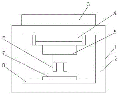
[0014] Such as figure 1 The shown automatic mechanical fixture includes: a fixture body 1; the outer end of the fixture body 1 is provided with a support frame body 2, and the top end of the support frame body 2 is provided with a central controller 3. The upper end of the supporting frame body 2 is provided with a moving tank body 4, and the lower end of the moving tank body 4 is provided with a telescopic arm 5, and the lower end of the telescopic arm 5 is provided with a clamp 6. The inner bottom end is provided with a mobile discharge table 7, and the lower end of the mobile discharge table 7 is provided with a workbench 8;

[0015] Wherein, the central controller 3 is set as a computer host, and its computer host is a single-chip microcomputer, and the central controller 3 is also connected with a remote controller;

[0016] The telescopic arm 5 is configured as a hydraulic telescopic arm;

[0017] The inner wall end of the clamp 6 is also provided with tooth lines.

...


PUM


Abstract

The invention discloses an automatic mechanical clamp. The automatic mechanical clamp comprises a clamp body. A supporting frame body is arranged at the outer end of the clamp body. A central controller is arranged at the top end of the supporting frame body. A movable tank body is arranged at the upper end of the interior of the supporting frame body. A telescopic boom is arranged at the lower end of the movable tank body. A clamp unit is arranged at the lower end of the telescopic boom. A movable charging table is arranged at the inner bottom end of the supporting frame body. A workbench is arranged at the lower end of the movable charging table. The automatic mechanical clamp is simple and reasonable in structure, convenient to use, efficient in operation, durable and capable of reliving the work intensity, improving the working efficiency and meeting the requirements of economic development.

Description

technical field [0001] The invention relates to an automatic mechanical fixture, which belongs to the field of mechanical equipment. Background technique [0002] At present, most of the transfer stations use manual loading and transportation, but the efficiency of manual loading is low and the labor cost is high. In order to improve the transfer efficiency during work, it is necessary to develop an automated mechanical fixture. Contents of the invention [0003] (1) Technical problems to be solved [0004] In order to solve the above problems, the present invention proposes an automatic mechanical fixture with simple and reasonable structure, convenient use, efficient operation, durability, reduced working intensity and increased working efficiency. [0005] (2) Technical solution [0006] An automatic mechanical fixture of the present invention comprises: a fixture body; a support frame body is provided at the outer end of the fixture body, a central controller is prov...

Claims


Application Information

Patent Timeline
Patent Type & Authority Applications(China)
IPC IPC(8): B25B11/00
CPCB25B11/00
Inventor 不公告发明人
Owner 温州兴南环保科技有限公司
Learn More