

Spanner with adjustable moment of force
A force-adjusting and wrench technology, applied in the directions of wrenches, screwdrivers, manufacturing tools, etc., can solve problems such as inconvenience in use and cost, and achieve the effect of simple structure, satisfying use needs and convenient use.
- Summary
- Abstract
- Description
- Claims
- Application Information
AI Technical Summary
Problems solved by technology
Method used
Image

Examples
Embodiment
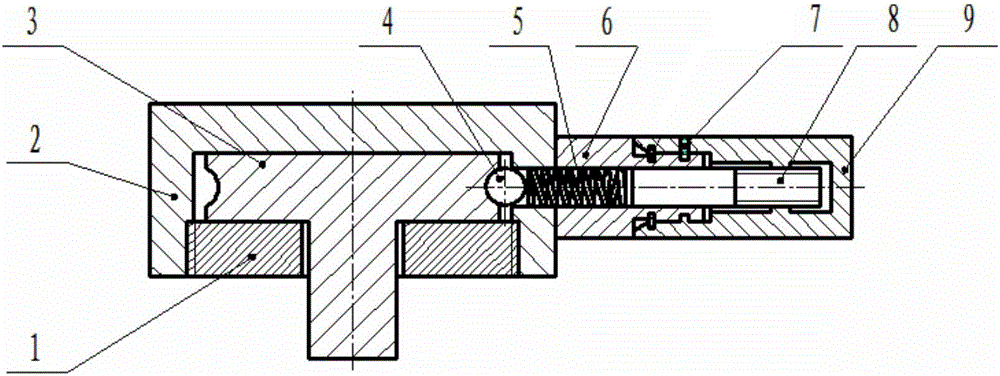
[0021] A kind of adjustable torque wrench of the present invention, as figure 1 As shown, it includes housing 2, lower baffle 1, wrench body 3, handle, ball 4, spring 5, and adjusting screw 8;
[0022] The housing 2 is a cylindrical member with an open lower end, the inner wall of the opening port of the housing 2 is processed with connecting threads, and the side wall of the housing 2 is provided with a ball passing hole;
[0023] The lower baffle 1 is a disc-shaped structure whose side wall is processed with an external thread matching the thread of the opening port of the shell 2, and the center of the lower baffle 1 is provided with a wrench hole;
[0024] The upper end of the wrench body 3 is a cylindrical section whose outer diameter matches the inner diameter of the inner cavity of the housing 2. The side wall of the cylindrical section is provided with hemispherical grooves uniformly distributed around the circumference, and a wrench rod extends vertically downward fro...
PUM
 Abstract
Description
Claims
Application Information