Suction device with a dirt collection chamber, a spinning machine, and a method

A suction device, spinning machine technology, used in textiles and papermaking, etc., can solve problems such as inability to remove sticky dirt, expensive suction devices, adverse effects, etc.

Inactive Publication Date: 2017-03-22
MASCHINENFABRIK RIETER AG
View PDF8 Cites 0 Cited by
  • Summary
  • Abstract
  • Description
  • Claims
  • Application Information

AI Technical Summary

Problems solved by technology

However, this type of cleaning is only suitable for removing dirt from suction devices used to suction fibrous structures
Because on the one hand the relatively high suction air flow has a det

Method used


Image

  • Suction device with a dirt collection chamber, a spinning machine, and a method
  • Suction device with a dirt collection chamber, a spinning machine, and a method
  • Suction device with a dirt collection chamber, a spinning machine, and a method

Examples


Embodiment Construction

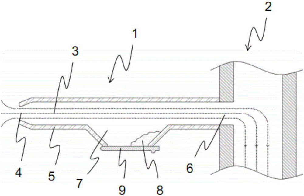
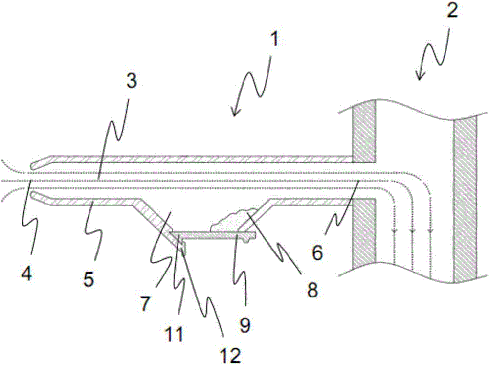
[0065] Figure 1a A longitudinal section through the suction device 1 and the partial vacuum device 2 connected to the suction device 1 is shown. A suction air flow 3 which can guide loose fibres, dirt and fibrous structures (not shown here) enters the suction device 1 through a suction opening 4 . The suction flow 3 continues along a line section 5 through a connection opening 6 into the partial vacuum device 2 . Furthermore, a dirt collection chamber 7 is shown, in the region of which the suction flow 3 is significantly reduced. Dirt 8 thus accumulates in the dirt collection chamber 7 without clogging in other areas of the pipe section 5 . Dirt collection chamber one side is designed with movable slide block 9. Slider 9 is in the working position in this figure.

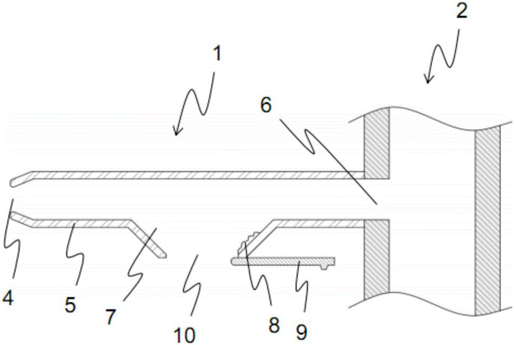
[0066] After a certain amount of dirt 8 has accumulated in the dirt collection chamber 7, the suction device 1 must be cleaned. To do this move slider 9 to Figure 1b In the cleaning position shown, the dirt c...


PUM


Abstract

The invention relates to a suction device (1) for a spinning machine with at least one suction opening (4) arranged at one end of the suction device (1) for sucking off a fiber structure, a connection opening (6) arranged at the other end for connection to a vacuum device (2), which is arranged between the two ends, is arranged on the pipe section (5) and is used to accumulate debris deposits (8),which is movable between at least one working position (15) and at least one cleaning position (16), is formed as a part of the dust collecting space (7). According to the invention, an opening (10) in the dirt collecting chamber (7) is cleared in the cleaning position (16) for cleaning the dirt collecting space (7). Furthermore, the invention relates to a spinning machine with a plurality of spinning stations which each have a drafting device and a drier generating device, and with an exhaust system which has at least one suction device (1) according to the preceding description. The invention also relates to a method for the extraction of loose fibers, dirt and fiber structures with a suction device (1) according to the preceding description.

Description

technical field [0001] The invention relates to a suction device for a spinning machine, the suction device is arranged at one end with at least one suction opening for suctioning a fiber structure, and at the other end is arranged with a connection opening for connecting to a negative pressure device, and between the two ends a pipe section is arranged, wherein a dirt collection chamber with an enlarged cross-sectional area is arranged in the pipe section for collecting dirt deposits, and the area of ​​the pipe section and / or the dirt collection chamber is formed in the A movable element between at least one working position and at least one cleaning position. Furthermore, the invention relates to a spinning machine with a plurality of spinning zones, each with a drafting device and a vortex generator, the spinning The machine is also provided with a suction device, and the invention also relates to a method for suctioning loose fibres, dirt and fibrous structures by means o...

Claims


Application Information

Patent Timeline
IPC IPC(8): D01H11/00
CPCD01H11/005
Inventor G·斯塔莱克
Owner MASCHINENFABRIK RIETER AG
Why Eureka
Try Eureka