Supercharge Your Innovation With Domain-Expert AI Agents!

A tunnel central drainage pipe and its laying method

A tunnel center and laying method technology, applied in drainage, mining equipment, earthwork drilling and mining, etc., can solve the problem of inability to maintain the straightness or gradient of the central drainage pipe, the reduction of the water permeability of the central drainage pipe, and the blockage of the central drainage pipe drain hole, etc. problems, to achieve the effect of ensuring stability and drainage, preventing clogging and avoiding rotation

Active Publication Date: 2019-04-05
CHINA RAILWAY ENG CONSULTING GRP CO LTD +2
View PDF10 Cites 0 Cited by
  • Summary
  • Abstract
  • Description
  • Claims
  • Application Information

AI Technical Summary

Problems solved by technology

[0005] 1. The process is complicated
During the construction project, due to the lack of understanding of the drainage mechanism of the scheme by the construction personnel, the construction steps of the central drainage pipe seat are often omitted, and the central drainage pipe is directly placed on the inverted arch structure surface or in the central drainage ditch, causing the central drainage pipe to be damaged. Rolling, it is difficult to locate during the subsequent construction process, and it is impossible to maintain the straightness or gradient of the central drainage pipe, which affects the drainage effect;
[0006] 2. It is easy to cause the blockage of the drain hole of the central drain pipe
For the scheme where the central drainage pipe is at the lower part of the inverted arch structure, even if the pipe seat is installed, the circular central drainage pipe is easy to rotate on the pipe seat during the subsequent construction process, such as the drain hole on the pipe rotates to the pipe seat. The contact position will cause the blockage of the drain hole and reduce the water permeability of the central drain pipe

Method used


Image

  • A tunnel central drainage pipe and its laying method
  • A tunnel central drainage pipe and its laying method
  • A tunnel central drainage pipe and its laying method

Examples


Embodiment 1

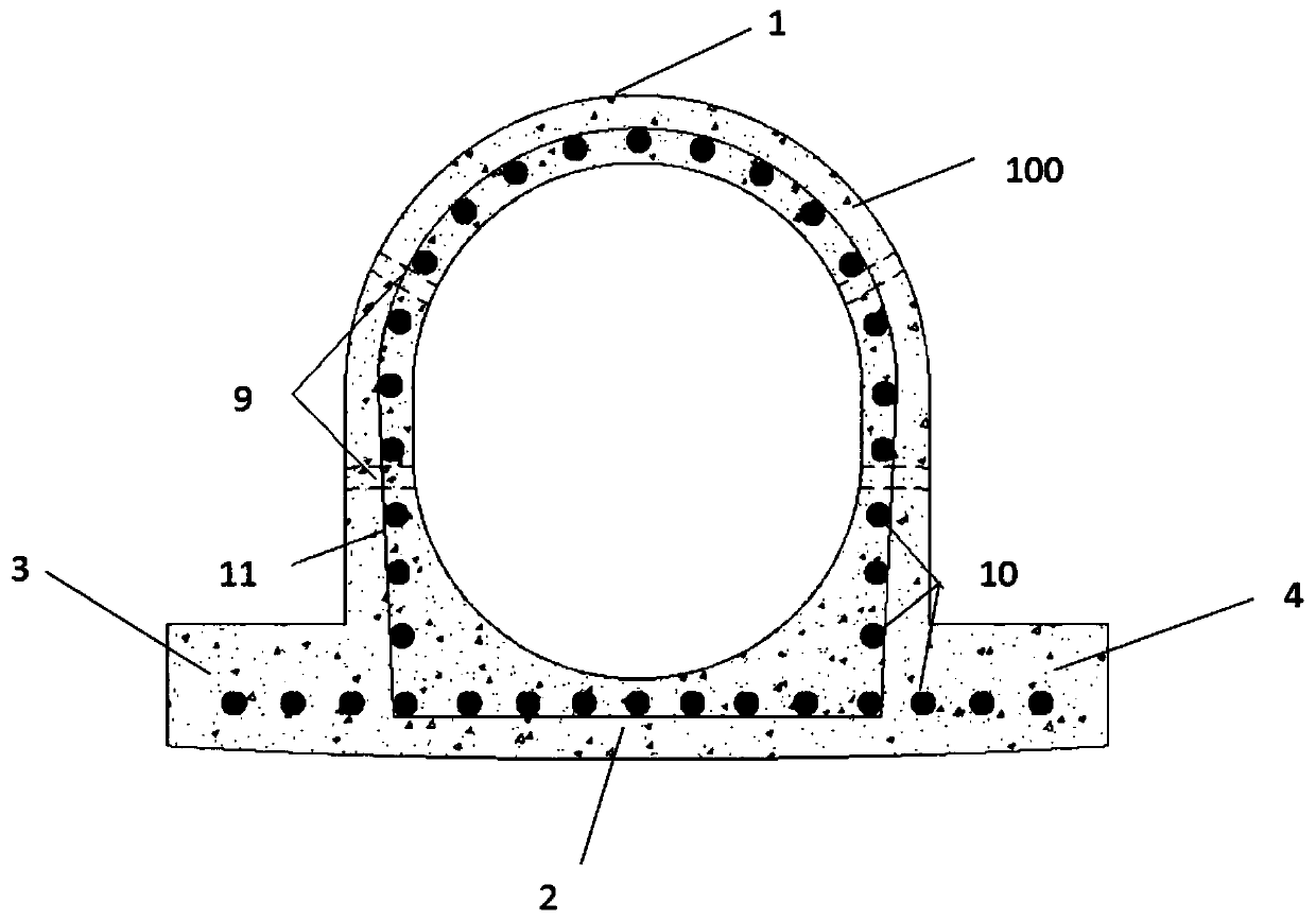
[0046] Such as figure 1 As shown, the tunnel central drainage pipe of the present invention includes a reinforced concrete pipe body 100, the cross section of which is arched, and the bottom of the pipe body 100 is flat, and the top 1 of the pipe body is arc-shaped. At the same time, the bottom 2 of the tube body has a first wing plate 3 and a second wing plate 4 extending to both sides of the tube body 100 along a direction perpendicular to the length of the tube body. Thus, the overall cross-section formed by the tube body 100 and the first wing plate 3 and the second wing plate 4 is roughly “Ω”, so it is not easy to shake and rotate, the setting of the tube seat can be omitted, and the process is simplified. .

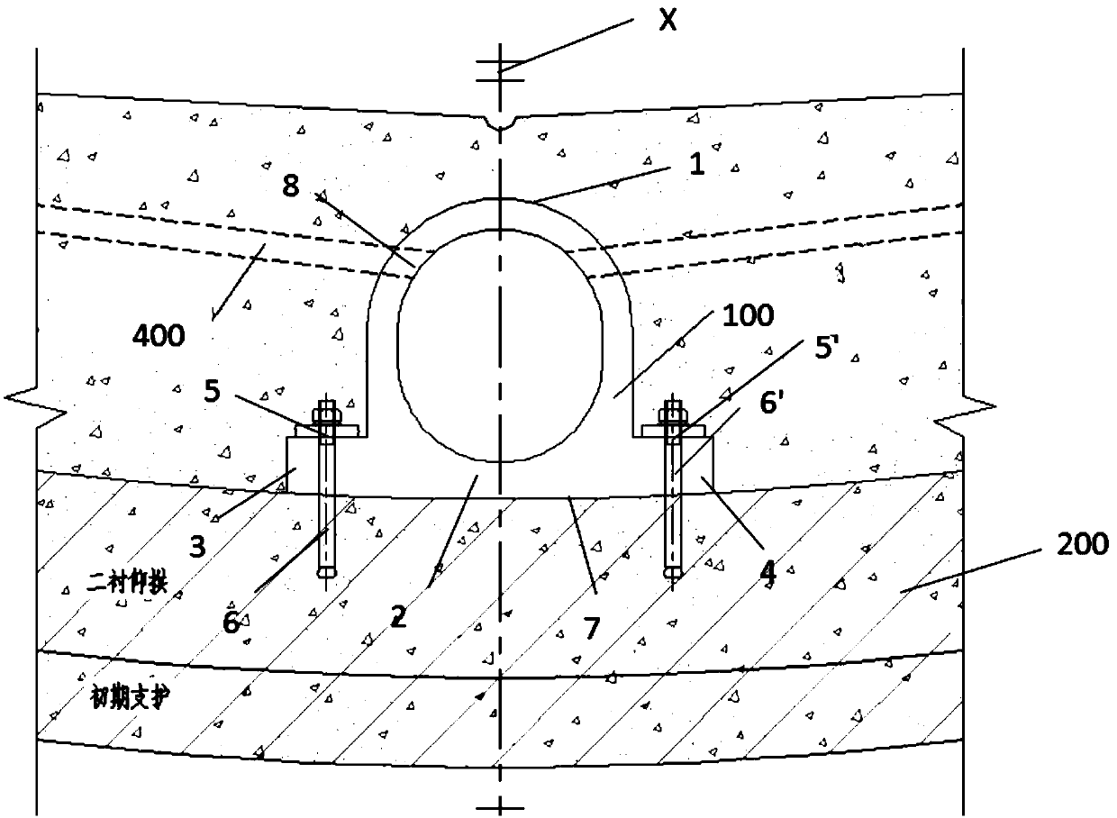
[0047] In this example, if figure 2 As shown, the pipe body 100 is arranged on the upper part of the inverted arch structure 200; the curvature of the top 1 is the same as that of the top surface of the inverted arch structure, and the arc-shaped pipe body top 1 ...

Embodiment 2

[0058] Such as Figure 4 As shown, the tunnel central drainage pipe of the present invention only includes a reinforced concrete pipe body 100', the cross section of the pipe body 100' is arched, and the bottom 2' of the pipe body is a plane. Similarly, the cross-section of the tube body 100' is non-traditionally circular, so it is not easy to shake and rotate, and the setting of the tube seat can be omitted, which simplifies the process.

[0059] Such as Figure 5 As shown, the pipe body 100' is disposed in the groove 500 below the center of the bottom of the inverted arch structure 200.

[0060] Concrete is sprayed on both side walls and the inner surface of the bottom of the groove 500 to form a first side wall concrete layer 12, a second side wall concrete layer 13 and a bottom concrete layer 14; the pipe body 100' is arranged on the On the bottom concrete layer 14 of the trench 500.

[0061] Preferably, in order to place the pipe body 100' stably, a C20 concrete leveli...


PUM


Abstract

The invention discloses a tunnel center drainage pipe. The tunnel center drainage pipe comprises a steel reinforced concrete pipe body, the cross section of the pipe body is in an arch shape, a plane serves as the bottom of the pipe body, the bottom of the pipe body can further extend towards the two sides of the pipe body in the direction perpendicular to the length direction of the pipe body so as to form a first wing plate and a second wing plate, and the pipe body is fixed to the upper portion of an inverted arch structure through fixing parts; and alternatively, the pipe body is directly arranged in a trench below the center of the bottom of the inverted arch structure. The cross section shape of the tunnel center drainage pipe is not round so that construction steps can be simplified, construction of a center drainage pipe seat can be omitted, the next working procedure can be carried out after the center drainage pipe is placed on the plane of the inverted arch structure or the bottom plane of the trench, and the working procedures are simplified. Meanwhile, rotation of the center drainage pipe can be avoided, and thus the center drainage pipe can meet the requirements of stability, straightness and the elevation in the subsequent construction process, blockage of a drainage hole is prevented, and the water permeability of the center drainage pipe is guaranteed.

Description

technical field [0001] The invention relates to the field of drainage pipe fittings, in particular to a tunnel central drainage pipe and a laying method thereof. Background technique [0002] With the continuous strengthening of national infrastructure construction, the number of various tunnel construction projects has gradually increased. Correspondingly, the number, scale and types of tunnel structural diseases are also on the rise. Among them, the main diseases of railway tunnel structure include: lining water leakage, lining cracking and bottom structure damage, which account for about 97% of all diseases. The emergence of such diseases as mud turning and side ditch damage is directly related to the quality of the drainage scheme at the bottom of the structure. [0003] At present, the main solution for tunnel drainage is side ditch plus central drainage pipe for drainage. The location of the central drainage pipe can be located on the upper part of the inverted arch s...

Claims


Application Information

Patent Timeline
Patent Type & Authority Patents(China)
IPC IPC(8): E21F16/02
CPCE21F16/02
Inventor 彭斌赵勇倪光斌林传年魏峰吕刚陈学峰刘建友郭磊陈志广王杨于鹤然刘方张矿三张延
Owner CHINA RAILWAY ENG CONSULTING GRP CO LTD
Features
  • R&D
  • Intellectual Property
  • Life Sciences
  • Materials
  • Tech Scout
  • Unparalleled Data Quality
  • Higher Quality Content
  • 60% Fewer Hallucinations
Learn More