Method for measuring prestressed anchor rod anchorage force relaxation loss rate

A measuring method and technology for anchoring force, applied in the field of geotechnical engineering, can solve the problems of complex installation, eccentric phenomenon, influence, etc., and achieve the effect of reducing potential safety hazards and ensuring smooth progress.

Active Publication Date: 2017-03-22
QINGDAO TECHNOLOGICAL UNIVERSITY
View PDF2 Cites 2 Cited by
  • Summary
  • Abstract
  • Description
  • Claims
  • Application Information

AI Technical Summary

Problems solved by technology

[0009] However, when the traditional anchor dynamometer is installed, the selected installation position is at the end of the anchor, so it is impossible to measure the stress distribution of the rest of the anchor body when the force is applied; in addition, the traditional anchor dynamometer not only The installation is more complicated and the cost is relatively high. During installation, the bolt dynamometer must be tightly connected with the bolt, and the bolt passes through the center of the bolt dynamometer, and the dynamometer is between the steel pedestal and the working anchor. , so that it can be used to measure the anchoring force of the anchor rod; and due to the limitations of its layout location and equipment, the measurement accuracy is greatly affected when the anchoring force of the anchor rod changes slowly
[0010] At the same time, due to the influence of various conditions during the tensioning process of the anchor rod, eccentricity will inevitably occur, that is, the load acting on the anchor pad is not uniformly distributed, and the eccentric force is not considered in the calculation formula of the anchoring force. problem, so this method will cause measurement error when measuring the anchoring force loss rate
[0011] In addition, during the monitoring operation, if one or more of the multiple sensors of the anchor dynamometer is damaged, the anchoring force change and anchoring force loss rate cannot be calculated.

Method used


Image

  • Method for measuring prestressed anchor rod anchorage force relaxation loss rate
  • Method for measuring prestressed anchor rod anchorage force relaxation loss rate
  • Method for measuring prestressed anchor rod anchorage force relaxation loss rate

Examples


Embodiment

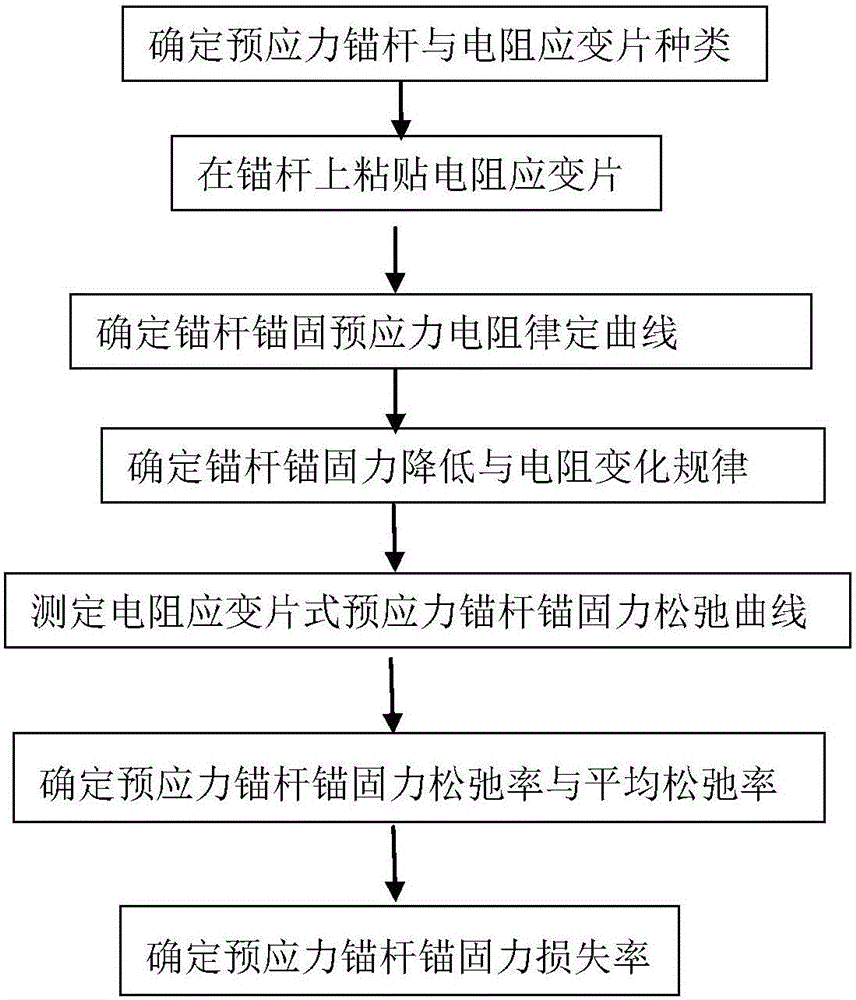
[0073] Embodiment: a method for determining the anchoring force relaxation loss rate of prestressed anchor bolts, using the anchor bolts on a rock mass slope as the detection object, the detailed steps include:

[0074] Step A: Fabrication and installation of the resistance strain gauge type prestressed anchor rod.

[0075] According to the "resistance strain gauge" test procedure (GB / T 13992-1992), the foil resistance strain gauge (resistance value is 1000Ω) is attached to the middle of the free section of the test anchor rod, and the test end of the strain gauge is led to the anchor head of the anchor rod , the operation process and installation of the strain gauge paste are as follows:

[0076] (1) Preparation of anchor rod pasting surface:

[0077] First remove the oil stains, paint, rust spots, electroplating layer, etc. on the surface of the anchor rod, and use emery cloth to cross-polish the fine lines to increase the adhesion, then scrub with a degreasing cotton ball ...


PUM

PropertyMeasurementUnit
diameteraaaaaaaaaa

Abstract

The invention relates to a method for measuring a prestressed anchor rod anchorage force relaxation loss rate, and belongs to the field of technologies related with geotechnical engineering. The main steps include A. installing a resistor disc and a wire on a prestressed anchor rod; B determining anchor rod anchoring prestress Pi and resistance Ri variation law curves; C. determining an anchor rod anchorage force reduction value [delta]Pi and resistance variation value [delta]Ri variation relation curve; D. determining [delta]Pt and [delta]Pt-t relaxation curves according to the curve obtained in the Step C; E. determining corresponding anchorage force relaxation rate [lambda]t and an average relaxation rate parameter at any time t; and F. determining a prestressed anchor rod anchorage force loss rate [eta]t. The method provided by the invention basically can measure the corresponding anchorage force relaxation rate at any time t after anchoring of the anchor rod, thereby providing an accurate basis for engineering progress, and reducing risks of disaster occurrence.

Description

technical field [0001] The invention relates to the related technical field of geotechnical engineering, in particular to a method for measuring the anchoring force relaxation loss rate of a prestressed bolt. Background technique [0002] Slope support is an important stability and effective reinforcement measure and method in many modern large-scale projects. As an important reinforcement and support method for slopes, anchor rods have the characteristics of low cost, good support effect and easy operation. [0003] However, due to the complexity of the engineering environment where it is located, the strength of anchoring materials and surrounding rocks, and the limitations of construction techniques, the anchoring force of the bolt often loses and decreases over time, causing the anchoring force to reach a certain level after a certain period of time. If the design requirements are not met, the reinforcement project will fail, which will not only bring huge economic losse...

Claims


Application Information

Patent Timeline
Patent Type & Authority Applications(China)
IPC IPC(8): G01L1/22
CPCG01L1/22
Inventor 贺可强张冰姜登坤
Owner QINGDAO TECHNOLOGICAL UNIVERSITY
Why Eureka
Try Eureka