Unlock instant, AI-driven research and patent intelligence for your innovation.

Calibration method for calibrating accuracy and linearity of Rogowski coil proportionality coefficient

A Rogowski coil and proportional coefficient technology, applied in the field of power frequency high current measurement, can solve the problems of inability to calibrate high current Rogowski coil linearity, low measurement accuracy, small calibration current, etc., to reduce human reading and calculation errors, reduce Calibration costs, the effect of reducing human error

Active Publication Date: 2017-03-22
XIAN HIGH VOLTAGE APP RES INST CO LTD
View PDF6 Cites 2 Cited by
  • Summary
  • Abstract
  • Description
  • Claims
  • Application Information

AI Technical Summary

Problems solved by technology

[0006] In order to solve the above problems, the present invention provides a calibration method for the accuracy and linearity of the proportional coefficient of the Rogowski coil, which solves the problem that the existing calibration method calibrates the proportional coefficient of the Rogowski coil with small calibration current and low measurement accuracy, and cannot calibrate large The technical problem of the linearity of the current Rogowski coil improves the measurement accuracy of the calibration ratio coefficient of the Rogowski coil, expands the calibration current, and can calibrate its linearity

Method used


Image

  • Calibration method for calibrating accuracy and linearity of Rogowski coil proportionality coefficient
  • Calibration method for calibrating accuracy and linearity of Rogowski coil proportionality coefficient
  • Calibration method for calibrating accuracy and linearity of Rogowski coil proportionality coefficient

Examples


Embodiment Construction

[0032] The specific embodiment of the present invention will be described in detail below in conjunction with the accompanying drawings, but the present invention is not limited to this embodiment. In order to provide the public with a thorough understanding of the present invention, specific details are specified in the following preferred embodiments of the present invention.

[0033] The method for calibrating the proportional coefficient of the Rogowski coil under the larger power frequency current of the present invention, the specific method is as follows:

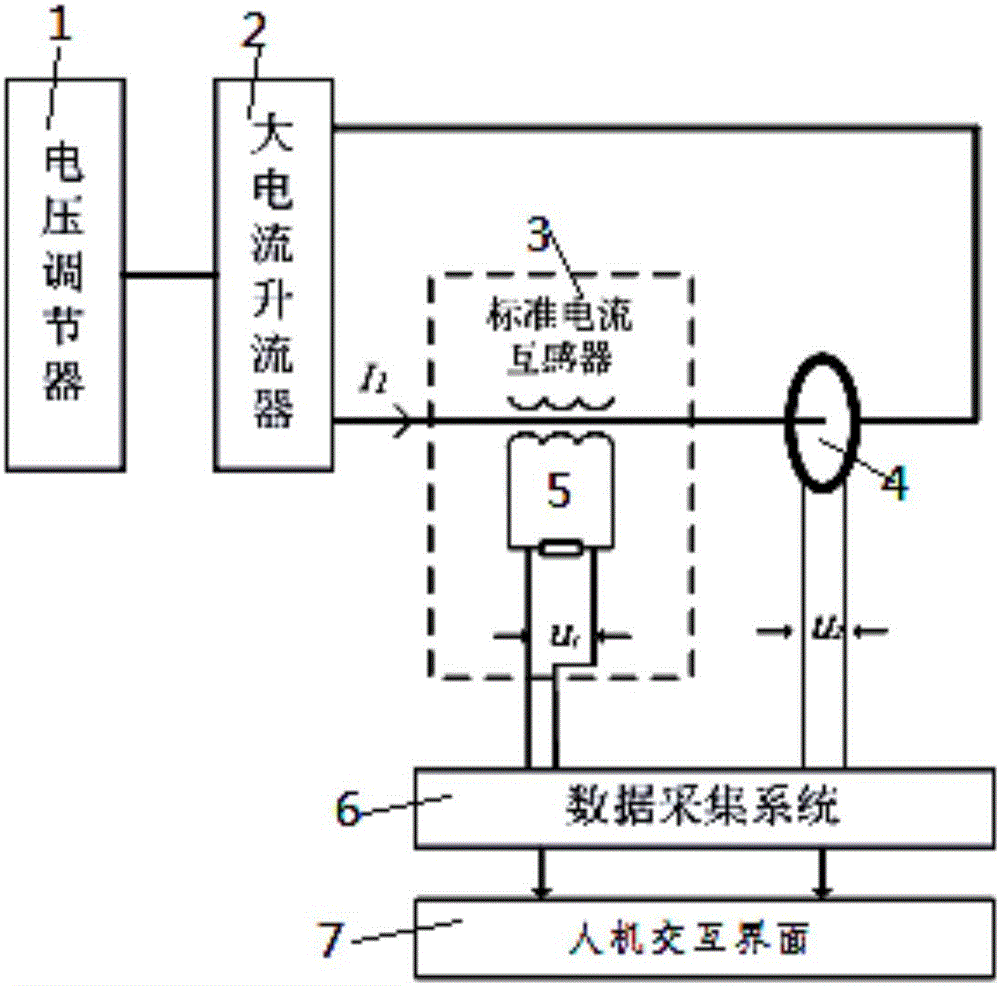
[0034] Such as figure 1As shown, a Rogowski coil proportional coefficient test system of the present invention includes a primary wire, a voltage regulator 1, a large current booster 2, a standard current transformer 3, a Rogowski coil 4, a standard resistor 5, a data acquisition system 6 and human Machine interface7. The voltage regulator 1 is connected to the high-current current booster 2, and the primary wire p...


PUM


Abstract

The present invention provides a calibration method for calibrating the accuracy and the linearity of a Rogowski coil proportionality coefficient and provides two calibration methods for calibrating the linearity of a Rogowski coil for the measurement of power-frequency large currents. According to the first method, N current branches with identical Rogowski coils are connected in parallel and then the current flows through the primary conductor of a to-be-calibrated Rogowski coil. The value of a primary current which flows through the to-be-calibrated Rogowski coil is equal to the sum of the values of primary currents which flow through the Rogowski coils of N current branches. In this way, the linearity of the proportionality coefficient is calculated and obtained. According to the second method, a current branch with a Rogowski coil is adopted. A primary current conductor passes through the primary loop of the to-be-calibrated Rogowski coil in the form of turns N. The value of the primary current which flows through the to-be-calibrated Rogowski coil is equal to N times the value of the primary current which flows through a calibrated Rogowski coil. In this way, the linearity of the proportionality coefficient is calculated and obtained. Based on the above method, the measurement accuracy of the Rogowski coil proportionality coefficient is improved, and the calibration current is expanded. Meanwhile, the linearity of a large-current Rogowski coil can be calibrated.

Description

[0001] 【Technical field】 [0002] The invention relates to the field of power frequency large current measurement, in particular to a calibration method for measuring the accuracy and linearity of the Rogowski coil proportional coefficient for power frequency large current. [0003] 【Background technique】 [0004] With the rapid development of high-voltage power transmission projects, large-capacity laboratories, measurement and protection of transmission and distribution networks, and industrial and mining enterprises have higher and higher requirements for accurate measurement of power frequency large currents. tool, the calibration of its measurement accuracy and linearity becomes very necessary. The accuracy of the existing Rogowski coil proportional coefficient is usually carried out by comparing the test with the standard shunt at a small current. The main disadvantage of this method is that the calibration current of the standard shunt is limited due to the limited curre...

Claims


Application Information

Patent Timeline
Patent Type & Authority Applications(China)
IPC IPC(8): G01R35/00
CPCG01R35/005
Inventor 任稳柱王安
Owner XIAN HIGH VOLTAGE APP RES INST CO LTD