High precision deformation monitoring device and method based on Beidou positioning

A deformation monitoring and Beidou positioning technology, which is applied in the field of high-precision deformation monitoring devices based on Beidou positioning, can solve the problems of increased use cost of total stations, inaccurate measurement data, affecting monitoring point settings, etc., so as to reduce observation costs and manpower. The effect of input, precise location and simple structure

Pending Publication Date: 2017-03-22
HUNAN LIANZHI BRIDGE & TUNNEL TECH
View PDF14 Cites 15 Cited by
  • Summary
  • Abstract
  • Description
  • Claims
  • Application Information

AI Technical Summary

Problems solved by technology

Although the total station can achieve high precision, there are many limitations in its use. For example, the total station relies on optical positioning, needs to be visible, and is greatly affected by weather factors; the total station needs to be used in conjunction with the observation station. In the process of long-term monitoring of geological deformation, the total station cannot be moved. When monitoring multiple locations, the cost of using the total station is greatly increased, and high-precision instruments are easily damaged when exposed to the field for a long time; in addition, Since the total station itself is also placed on the ground to be monitored, geological deformation may also cause deviations in the position of the total station, resulting in inaccurate measurement data. Therefore, the position setting of the total station is limited by geological conditions. Not only affects the setting of monitoring points, but also increases the additional workload

Method used


Image

  • High precision deformation monitoring device and method based on Beidou positioning
  • High precision deformation monitoring device and method based on Beidou positioning

Examples


Embodiment Construction

[0024] The following will clearly and completely describe the technical solutions in the embodiments of the present invention with reference to the accompanying drawings in the embodiments of the present invention. Obviously, the described embodiments are only some, not all, embodiments of the present invention. Based on the embodiments of the present invention, all other embodiments obtained by persons of ordinary skill in the art without making creative efforts belong to the protection scope of the present invention.

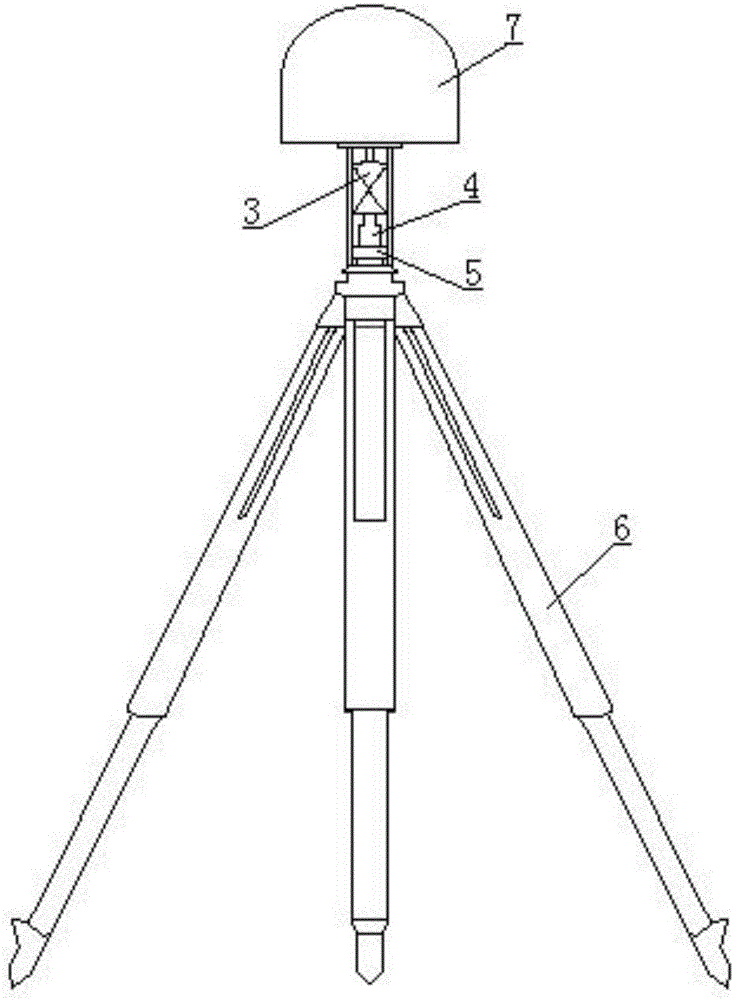
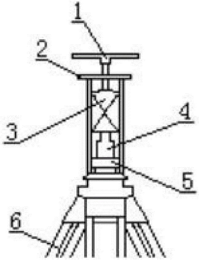
[0025] see figure 1 and figure 2 , a high-precision deformation monitoring device based on Beidou positioning, including a total station, multiple portable observation stations, and a central service station for information processing and data calculation. The portable observation stations include sequentially from top to bottom The Beidou positioning antenna 1, the forced centering device 2, the universal prism 3, the optical centering device 4, the levelin...


PUM


Abstract

The invention provides a high precision deformation monitoring device based on Beidou positioning. The device comprises a total station instrument, portable observation stations, and a center service station. Each of the portable observation stations comprises a Beidou positioning antenna, a forced centering device, a universal prism, an optical centering device, a leveling base and a tripod arranged from the top to bottom. Through the joint measurement solution of the Beidou positioning antenna and a near CORS station, the 3D coordinate A of each observation station is obtained, a coordinate system is subjected to network adjustment, at the same time the total station instrument and the universal prism are used to position the observation stations again in the coordinate system so as to obtain the 3D coordinate B of each observation station, through the comparison calculation of two coordinates, the actual initial coordinate of each observation station is corrected, the total station instrument is removed, and the deformation monitoring of the position is carried out through the change of the coordinates obtained by the Beidou positioning antenna. The monitoring device and method are simple and practical, the precision of the data measurement is high, the real-time monitoring can be realized, and the use cost of the total station instrument can be reduced.

Description

technical field [0001] The invention relates to the technical fields of geological disaster monitoring, geodetic surveying and engineering construction, in particular to a high-precision deformation monitoring device and method based on Beidou positioning. Background technique [0002] The process of monitoring geological disasters plays an important role in the analysis of its cause mechanism and forecasting and early warning. Due to the high-precision requirements for geological deformation monitoring, the existing monitoring technology mainly uses high-precision total stations. Although the total station can achieve high precision, there are many limitations in its use. For example, the total station relies on optical positioning, needs to be visible, and is greatly affected by weather factors; the total station needs to be used in conjunction with the observation station. In the process of long-term monitoring of geological deformation, the total station cannot be moved....

Claims


Application Information

Patent Timeline
Patent Type & Authority Applications(China)
IPC IPC(8): G01S19/40G01C15/00
CPCG01C15/00G01C15/002G01S19/40
Inventor 梁晓东
Owner HUNAN LIANZHI BRIDGE & TUNNEL TECH
Why Eureka
Try Eureka