Low-height biaxial deflection device having deflection axes intersected on surface of reflector and method

A deflection device and reflector technology, applied in installation, instrumentation, optics, etc., can solve the problems of large installation space, limited structural fundamental frequency, and reduced reliability, and achieve low vertical height, reduce optical path control errors, and respond fast effect

Active Publication Date: 2017-03-22
西安朗威科技有限公司
View PDF6 Cites 11 Cited by
  • Summary
  • Abstract
  • Description
  • Claims
  • Application Information

AI Technical Summary

Problems solved by technology

In response to this demand, piezoelectric ceramics and flexible hinge structures can be used to achieve multi-axis deflection, but there are still some problems in the current technology. First, the longitudinal dimensions of piezoelectric deflection mechanisms currently on the market are generally relatively high, and the required installation space The depth is large, and the height also limits the fundamental frequency of the structure, reducing reliability
Secondly, limited by the position design of the flexible hinge currently used, when the mirror output deflection angle, the center of the mirror surface will be displaced in the height direction, and the center of the mirror surface where the reflected light point is located does not intersect with the deflection axis of the structure, so the accuracy needs to be improved

Method used


Image

  • Low-height biaxial deflection device having deflection axes intersected on surface of reflector and method
  • Low-height biaxial deflection device having deflection axes intersected on surface of reflector and method
  • Low-height biaxial deflection device having deflection axes intersected on surface of reflector and method

Examples


Embodiment Construction

[0017] The present invention will be described in further detail below in conjunction with the accompanying drawings and specific embodiments.

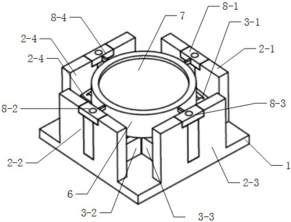
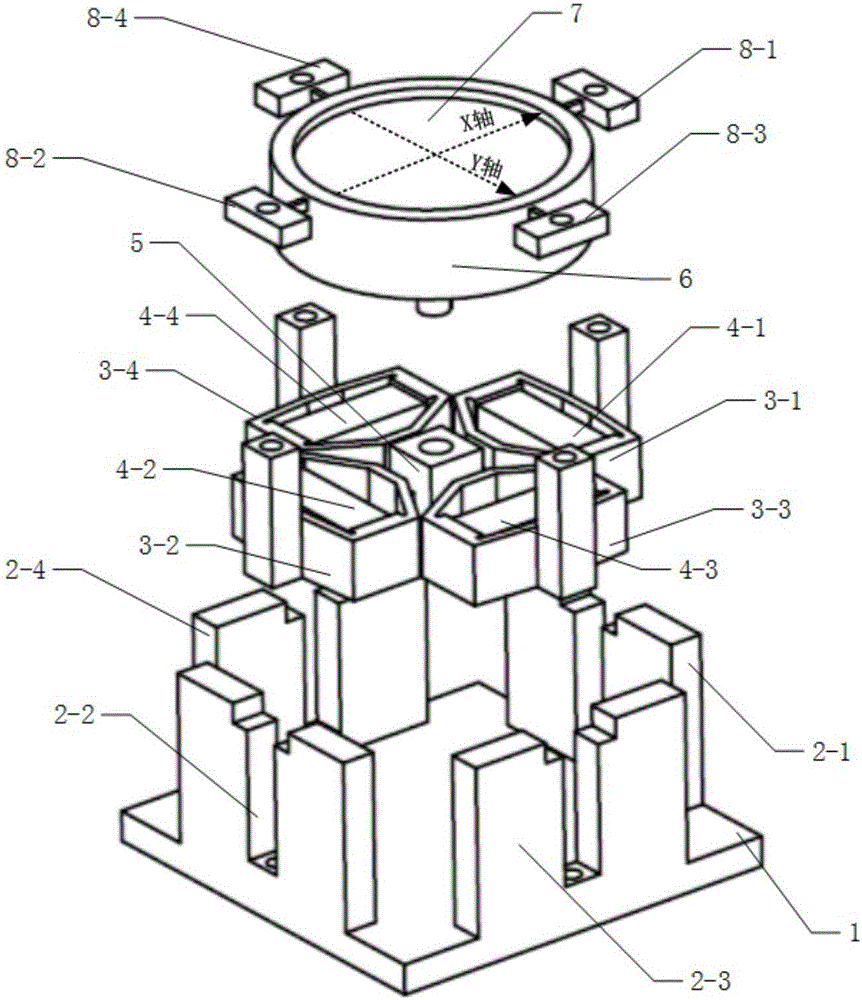
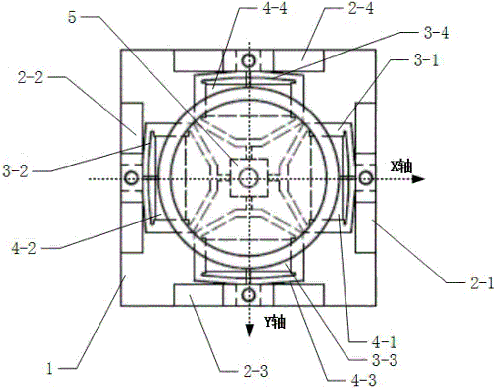
[0018] Such as figure 1 , figure 2 and image 3 As shown, a low-height biaxial deflection device of the present invention whose deflection axis intersects the mirror surface includes a base 1, a first fixed support 2-1, a second fixed support 2-2, and a base mounted on the base 1. The third fixed support 2-3 and the fourth fixed support 2-4, one end is fixed on the first elastic kite ring 3-1 on the first fixed support 2-1, and one end is fixed on the second fixed support 2 The second elastic kite-shaped ring 3-2 on the -2, the third elastic kite-shaped ring 3-3 fixed on the third fixed support 2-3 at one end, and the third elastic kite-shaped ring 3-3 fixed at the fourth fixed support 2-4 at one end The fourth elastic kite-shaped ring 3-4, the first piezoelectric ceramic 4-1 horizontally installed in the first elastic kite-shaped...


PUM


Abstract

The invention discloses a low-height biaxial deflection device having deflection axes intersected on the surface of a reflector and method. The deflection device is mainly composed of three parts: a base and a fixed support installed fixedly; an elastic kite-like ring and a deflection supporting seat for providing deflection drive; and a reflector bearing table, the reflector as well as a flexible hinge for constraining deflection displacement of the reflector bearing table and a connecting table thereof. The deflection device realizes output control of a deflection angle by using four piezoelectric ceramics, and has the characteristics of high control precision and quick response; the piezoelectric ceramics are divided into two groups, the piezoelectric ceramics in the same group are driven by adopting a differential manner to realize corresponding monoaxial deflection displacement, and the four piezoelectric ceramics are simultaneously driven to realize biaxial deflection of the reflector; the device adopts a structural form of reflector settlement, and the deflection axes are intersected on the surface of the reflector, so that the optical path control error caused by longitudinal displacement of the reflector surface is reduced; meanwhile, the device has a low and compact structural feature, and requires a small installation space.

Description

technical field [0001] The invention relates to a dual-axis deflection mirror device and an implementation method thereof, in particular to a low-height dual-axis deflection device and method in which deflection axes intersect the surface of the mirror. Background technique [0002] In recent years, astronomical telescopes, microscopes, and other precision optical systems have been widely used in aerospace engineering, reproductive technology and other fields, and higher requirements for precise optical path control have been put forward. In response to this demand, piezoelectric ceramics and flexible hinge structures can be used to achieve multi-axis deflection, but there are still some problems in the current technology. First, the longitudinal dimensions of piezoelectric deflection mechanisms currently on the market are generally relatively high, and the required installation space The depth is large, and the height also limits the fundamental frequency of the structure, ...

Claims


Application Information

Patent Timeline
IPC IPC(8): G02B7/198
CPCG02B7/198G02B26/101G02B26/0816G02B26/0858
Inventor 徐明龙宋思扬田征冯勃邵恕宝
Owner 西安朗威科技有限公司
Why Eureka
Try Eureka