Scanning probe

a scanning probe and probe body technology, applied in the field of scanning probes, can solve the problems of reducing the tracking capability of the measurement stylus to the surface of the workpiece, affecting the accuracy of measurement, and reducing the driving force of the measurement stylus, so as to eliminate the influence of inertial force and achieve high precision measurement

Active Publication Date: 2005-02-03
MITUTOYO CORP
View PDF10 Cites 17 Cited by
  • Summary
  • Abstract
  • Description
  • Claims
  • Application Information

AI Technical Summary

Benefits of technology

An object of the present invention is to provide a scanning probe, which can provide high speed response by ensuring the tracking capability thereof and also can sufficiently improve the precision in measurement.
With the configuration as described above, a measuring force can be adjusted by providing feedback controls to a fine feeder so that a contacting force will be within a predefined range and also by driving the probe body and a measurement stylus with the controlled fine feeder. Because of the feature, it is possible to provide controls so that the measuring force is minimized and maintained at a constant level, and therefore the tracking capability thereof is ensured with the high speed response in measurement realized and also with the precision in measurement improved.
Further by removing an inertial force acting over the measurement stylus moving with acceleration from the contacting force with a contacting force adjuster, it is possible to correct an error in measurement, so that a correct measuring force can be obtained. Because of this feature, influence of acceleration over the precision in measurement can be eliminated, and high precision measurement including no error can be executed even with a small measuring force. Therefore, even when the scanning probe is driven, for instance, with a driving arm of a surface texture measurement instrument so that the moving speed is rapidly raised from a low level to a high level (namely, so that large acceleration acts) for carrying out high speed scanning, the high precision in measurement can be maintained.
With the configuration as described above, as the fine feeder includes a three-axes slider and an actuator, a probe body and a measurement stylus can be driven in each direction of the three axis slider by controlling the actuator by means of feed back controller. Therefore, especially when the scanning probe according to the present invention is used in a coordinate measuring machine, a measuring force in each of the three dimensional directions can be adjusted, so that the high precision in measurement can further be improved.
With the configuration as described above, the contacting force adjuster includes a weight, a pantograph mechanism, and a gimbal mechanism, and when an inertial force acting to the weight is balanced with that acting to the measurement stylus, the inertial force acting to the measurement stylus is removed from the contacting force (measuring force), so that a correct contacting force can be detected by the contacting force detecting means. Therefore it is possible to eliminate the influence of an inertial force cased by acceleration and to execute high precision measurement.
With the configuration as described above, the contacting force adjuster includes an acceleration sensor, and an inertial force acting to the measurement stylus is computed based on acceleration of the measurement stylus detected by the acceleration sensor, and also the computed inertial force is removed from the contacting force (measuring force) detected by the contacting force detector, so that a correct measuring force can be obtained. Therefore, it is possible to eliminate the influence by the inertial force caused by acceleration and to carry out high precision measurement.

Problems solved by technology

With the scanning probe described in the aforesaid reference, however, when a measuring force is minimized by controlling the measuring force generator, also a driving force for a measurement stylus is reduced, and the tracking capability of the measurement stylus to a surface of a workpiece becomes lower.
Further, as a weight of a movable portion operating together with the measurement stylus is large, when a measuring force is reduced, acceleration acting over the measurement stylus when driving the scanning probe may affect the precision in measurement.
Therefore, the inertial force not causing any severe problem when the measuring force is large may sometimes affect a result of measurement as an error measurement and disadvantageously make it impossible to obtain the desired precision in measurement.

Method used


Image

  • Scanning probe
  • Scanning probe
  • Scanning probe

Examples


second embodiment

FIGS. 1 through 5 show a first embodiment of the present invention, and FIGS. 6 and 7 show the present invention.

first embodiment

[First Embodiment]

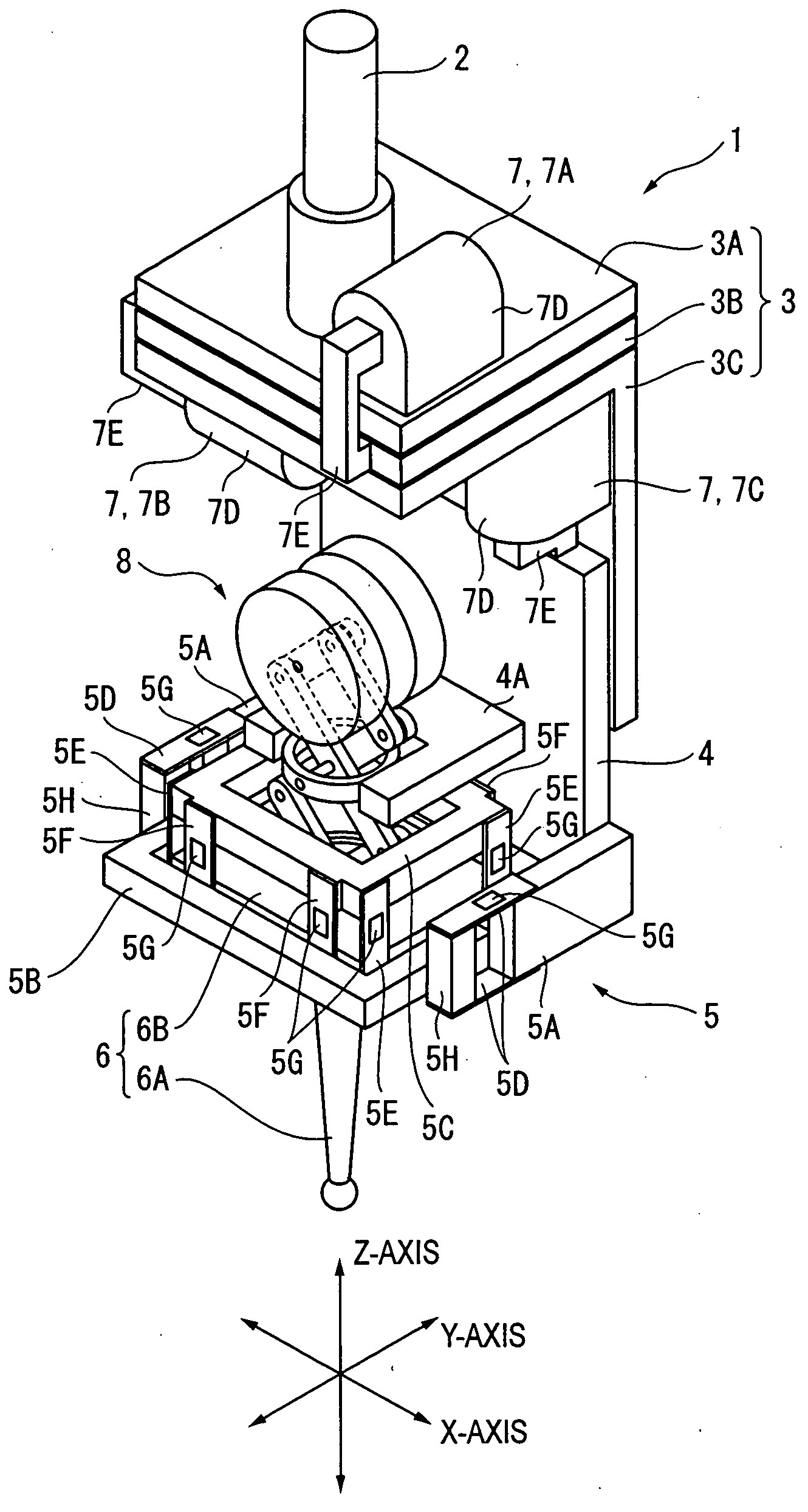
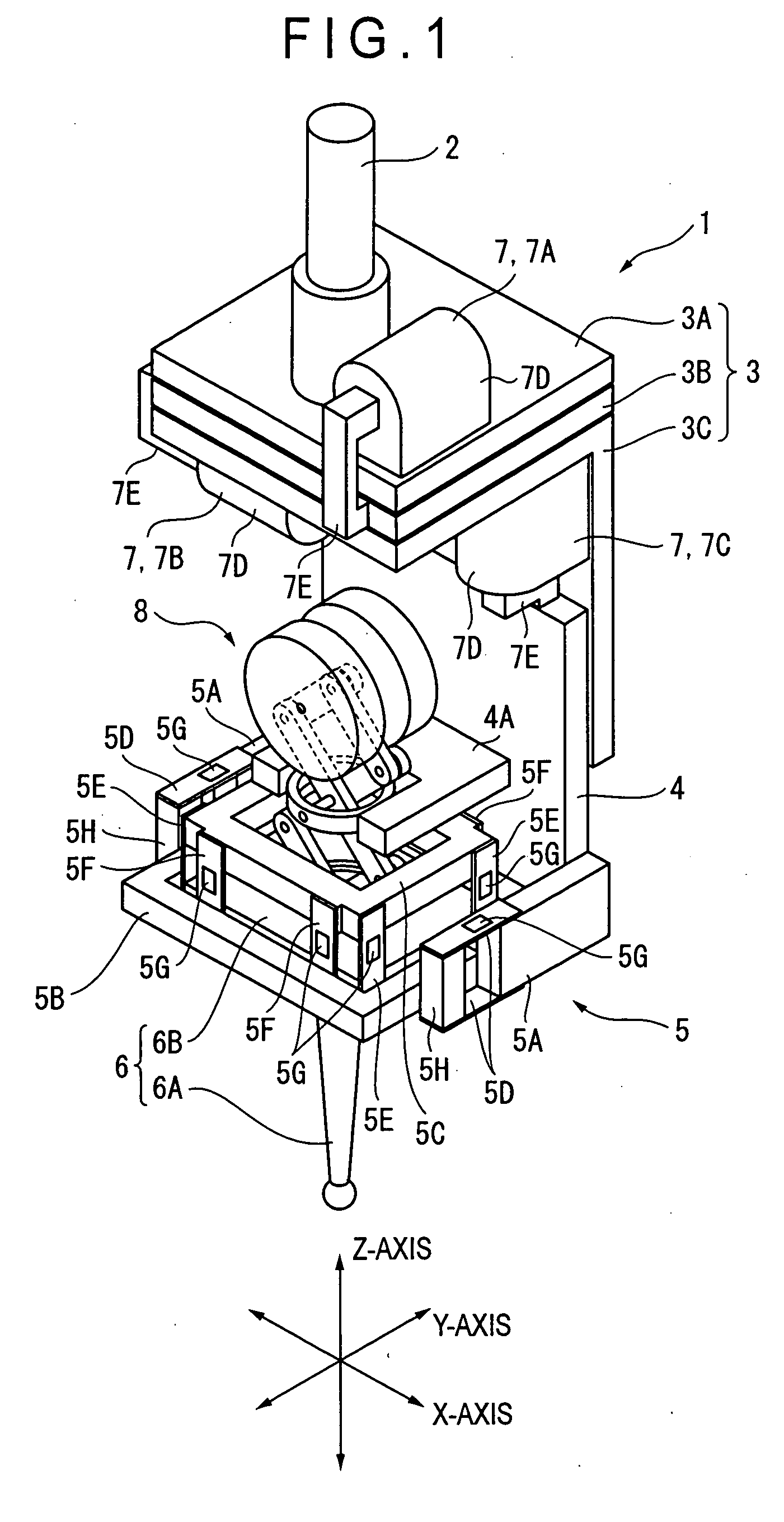
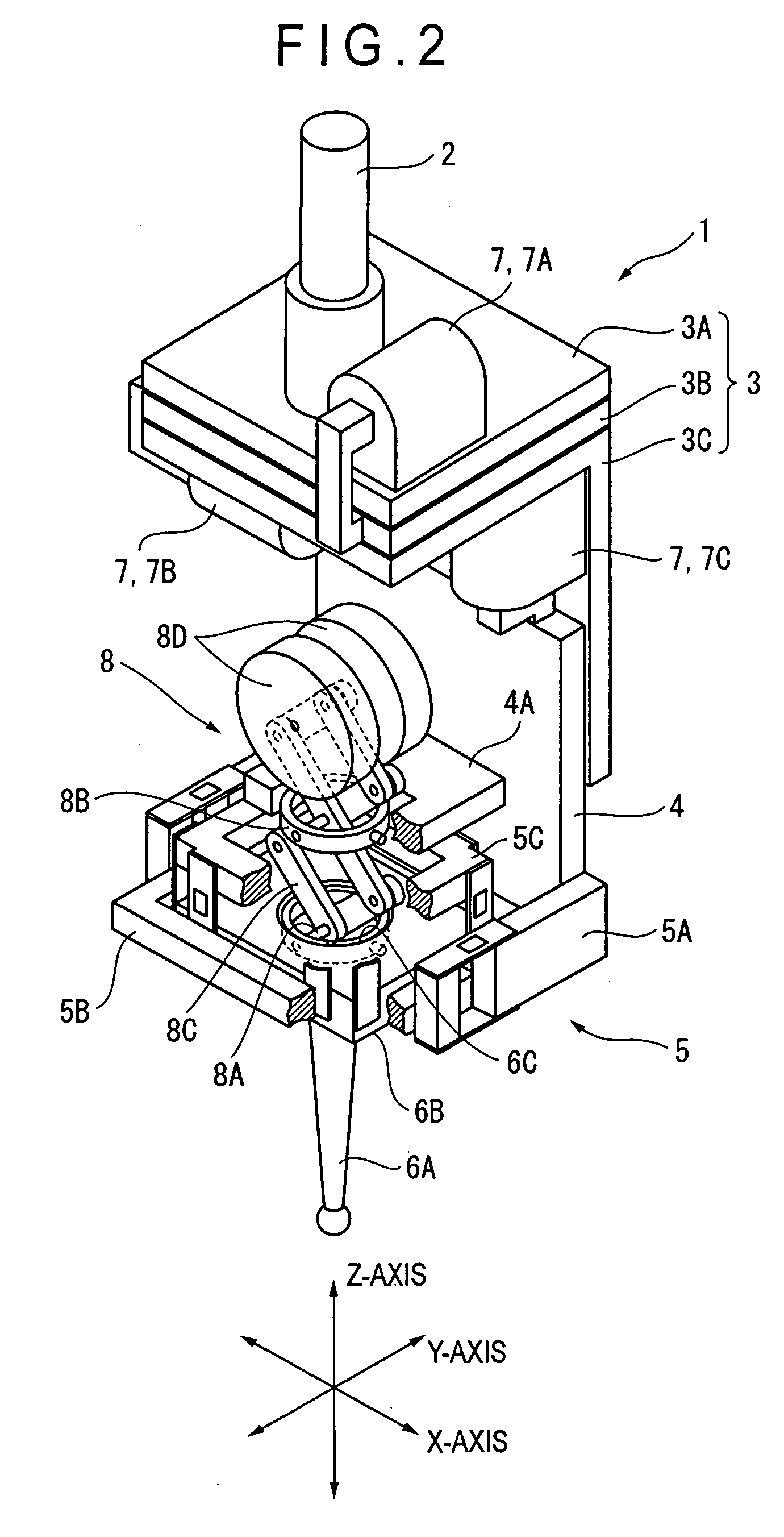
FIG. 1 is a perspective view showing a scanning probe 1 according to a first embodiment. FIG. 2 is a perspective view showing a partial cross section of the scanning probe 1. FIG. 3 and FIG. 4 are side elevations illustrating operations of a contacting force adjuster provided in the scanning probe 1. FIG. 5 is an explanatory view showing a procedure of measurement with the scanning probe 1.

InFIG. 1, the scanning probe 1 includes a mounting shaft 2 mounted on a driving arm of a coordinate measuring machine not shown in the figures, and is driven in each of the three directions (X, Y, and Z directions) perpendicular to each other in association with movement of the driving arm. Namely the scanning probe 1 in FIG. 1 is a three-dimensional scanning probe based on the contact system which is driven in two horizontal directions (X and Y directions) along a surface of an object to be measured (workpiece) not shown in the figures and placed below the scanning probe 1 and...


PUM


Abstract

A scanning probe (1, 10) according to the present invention includes a measurement stylus (stylus) (6) movably supported via elastic members (5D, 5E, 5F) on a probe body (4), fine feeders (3, 7) for moving the probe body (4) and the measurement stylus (6) against a workpiece within a fine range, a contacting force detector (5G) for detecting a contacting force between the measurement stylus (6) and a surface of the workpiece, and a contacting force adjuster (8) for adjusting the contacting force by removing the inertial force acting to the measurement stylus (6) because of acceleration from the contacting force. Because of this feature, a measuring force can be adjusted by providing feedback controls to the fine feeders (3, 7), so that the tracking capability is ensured to provide a high response rate and high precision in measurement. Further by eliminating influence of the inertial force of the measurement stylus (6), a measurement error is corrected to obtain a correct measuring force, and high precision measurement can be executed.

Description

BACKGROUND OF THE INVENTION 1. FIELD OF THE INVENTION The present invention relates to a scanning probe. More specifically this invention relates to a scanning probe based on the contact system, which is driven along a surface of an object to be measured. 2. DESCRIPTION OF RELATED ART In a scanning probe used, for instance, in a surface texture measuring instrument for measuring roughness or waviness of a surface of an object to be measured (workpiece), it is important for improving the measuring accuracy to minimize a contacting force (measuring force) between a tip of a measurement stylus (stylus, contact needle) and a surface of a workpiece and maintain the contacting force at a constant level. There has been proposed a scanning probe, a measuring force of which can be minimized and maintained at a constant level (Refer to, for instance, Japanese Patent Laid-Open Publication No. Hei 8-43066). The scanning probe described in the reference (a probe head of a coordinate measuri...

Claims


Application Information

Patent Timeline
Patent Type & Authority Applications(United States)
IPC IPC(8): G01B5/20F16F7/10G01B3/00G01B5/012G01B21/04
CPCF16F7/10F16F2230/0052G01B21/045G01B5/012G01B3/008
Inventor YAMAMOTO, TAKESHIAKAIKE, TAKENORIMIEDA, KATSUHIKO
Owner MITUTOYO CORP
Why Eureka
Try Eureka