Vibration transmission inductor system

A technology of vibration sensing and vibration transmission, which is applied in the directions of instruments, electrical digital data processing, user/computer interaction input/output, etc. It can solve problems such as the dead angle of the oscillator, the difficulty of guaranteeing user experience, and the large trigger blind area, etc., to achieve Enhance the comfort of use, improve the success rate and use experience, and reduce the effect of blind spots

Active Publication Date: 2017-03-22
GD MIDEA AIR-CONDITIONING EQUIP CO LTD +1
View PDF6 Cites 0 Cited by
  • Summary
  • Abstract
  • Description
  • Claims
  • Application Information

AI Technical Summary

Problems solved by technology

However, there is a dead angle in the direction of the external force and the oscillator inside the vibration sensor, whether the vibration sensor is placed horizontally or vertically, such as Figure 1b As shown, relatively large...

Method used


Image

  • Vibration transmission inductor system
  • Vibration transmission inductor system
  • Vibration transmission inductor system

Examples


Embodiment Construction

[0045] In order to understand the above-mentioned purpose, features and advantages of the present invention more clearly, the present invention will be further described in detail below in conjunction with the accompanying drawings and specific embodiments. It should be noted that, in the case of no conflict, the embodiments of the present application and the features in the embodiments can be combined with each other.

[0046] In the following description, many specific details are set forth in order to fully understand the present invention. However, the present invention can also be implemented in other ways different from those described here. Therefore, the protection scope of the present invention is not limited by the specific details disclosed below. EXAMPLE LIMITATIONS.

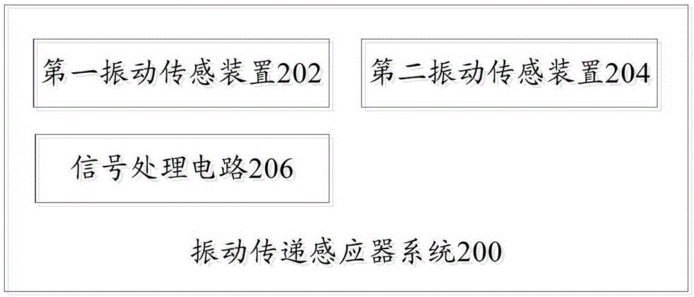
[0047] like figure 2 As shown, a schematic block diagram of a vibration transmission sensor system 200 according to an embodiment of the present invention:

[0048] The first vibration sensing dev...


PUM


Abstract

The invention provides a vibration transmission inductor system. The system comprises a first vibration sensing apparatus for sensing a vibration in a first stress direction, a second vibration sensing apparatus arranged in a manner of forming a first preset angle alpha with the first vibration sensing apparatus and used for sensing a vibration in a second stress direction, and a signal processing circuit, wherein the first vibration sensing apparatus and the second vibration sensing apparatus are connected in parallel to form a combined vibration sensing apparatus; and the combined vibration sensing apparatus is connected to the input end of the signal processing circuit. Through the technical scheme, stress blind regions can be greatly reduced and pat of a user in any direction can be induced, so that the problems of a large triggering blind region and numerous stress dead angles caused by adoption of a single vibration sensor in related technologies are avoided, the user can trigger a vibration apparatus without performing patting for multiple times or vigorously, the usage comfort is greatly enhanced, and the success rate of user operation and the usage experience are increased and improved.

Description

technical field [0001] The invention relates to the technical field of home appliances, in particular to a vibration transmission sensor system. Background technique [0002] More and more sensors are widely used in smart home appliances, and people hope to increase the comfort and quality of use of home appliances. Some traditional household appliances use vibration transmission sensors. The way users control and interact is to tap the external force to trigger the vibration sensor to realize the set function. However, if a single vibration sensor is used, due to the restriction of the direction of the external force or the different magnitude of the force, a large number of actions cannot be triggered, so multiple taps are required. [0003] like Figure 1a As shown, the circuit schematic diagram of the vibration transmission sensor in the related art. A vibration sensor and a pull-up resistor are used to form a detection circuit. When vibration or displacement occurs, t...

Claims


Application Information

Patent Timeline
IPC IPC(8): G06F3/01
CPCG06F3/011
Inventor 杨春喜
Owner GD MIDEA AIR-CONDITIONING EQUIP CO LTD
Why Eureka
Try Eureka