Drive circuit and display device

A technology for driving circuits and driving signals, applied in static indicators, instruments, etc., can solve problems such as increasing power consumption and large impedance, and achieve the effects of preventing short circuits, reducing losses, and reducing power consumption

Inactive Publication Date: 2017-03-22
TCL CHINA STAR OPTOELECTRONICS TECH CO LTD
View PDF11 Cites 0 Cited by
  • Summary
  • Abstract
  • Description
  • Claims
  • Application Information

AI Technical Summary

Problems solved by technology

However, the existing fan-out line is a single-layer metal layer, resulting in a relatively large impedance, thereby increasing power consumption

Method used


Image

  • Drive circuit and display device
  • Drive circuit and display device
  • Drive circuit and display device

Examples


Embodiment Construction

[0028] The following descriptions of the various embodiments refer to the accompanying drawings to illustrate specific embodiments in which the present invention can be practiced. The directional terms mentioned in the present invention, such as "up", "down", "front", "back", "left", "right", "inside", "outside", "side", etc., are for reference only The orientation of the attached schema. Therefore, the directional terms used are used to illustrate and understand the present invention, but not to limit the present invention. In the figures, structurally similar units are denoted by the same reference numerals.

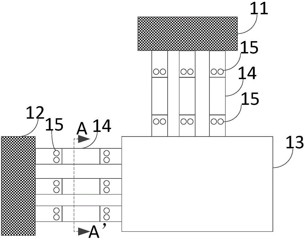
[0029] Please refer to Figures 1 to 3 , figure 1 It is a structural schematic diagram of the display device of the present invention.

[0030] Such as figure 1 As shown, the driving circuit includes a driving chip and at least two strip-shaped fan-out parts 14; wherein the driving chip includes a source driving chip 11 and a gate driving chip 12, the source drivi...


PUM


Abstract

The present invention provides a drive circuit and a display device. The drive circuit comprises a drive chip used for providing a drive signal; at least two strip-shaped fan-out parts used for transmitting the drive signal to the display region of the display panel, wherein each strip-shaped fan-out part is composed of a first metal layer and a second metal layer and the second metal layer is located on the first metal layer. The width of the second metal layer is smaller than the width of the first metal layer. According to the technical scheme of the drive circuit and the display device, the power consumption can be reduced.

Description

[0001] 【Technical field】 [0002] The invention relates to the technical field of displays, in particular to a driving circuit and a display device. [0003] 【Background technique】 [0004] With the continuous development of the display panel, the driving technology for the display panel is also continuously developed. Existing display panels generally include an array substrate and a color filter substrate. A plurality of data lines, a plurality of scan lines and a plurality of pixel units defined by the data lines and the scan lines are arranged on the array substrate. [0005] In order to drive the display panel, generally a driver chip is disposed on the periphery of the display panel, that is, the driver chip is located in a non-display area. The driving chip is used for providing driving signals, and the driving signals include data signals and scanning signals. The driving chip is connected to the scanning line and the data line through the fan-out line, so as to tran...

Claims


Application Information

Patent Timeline
Patent Type & Authority Applications(China)
IPC IPC(8): G09G3/36
CPCG09G3/20G09G3/36
Inventor 甘启明张君恺
Owner TCL CHINA STAR OPTOELECTRONICS TECH CO LTD
Why Eureka
Try Eureka