A pressure control method and device

A technology of pressure value and chamber pressure, applied in transportation and packaging, electrical components, conveyor objects, etc., can solve the problem of long waiting time for pressure recovery of TC chamber, and achieve the effect of shortening pressure recovery time and improving efficiency

Active Publication Date: 2020-03-31
BEIJING NAURA MICROELECTRONICS EQUIP CO LTD
View PDF6 Cites 0 Cited by
  • Summary
  • Abstract
  • Description
  • Claims
  • Application Information

AI Technical Summary

Problems solved by technology

[0007] In view of the above problems, the present invention is proposed to solve the problem of long waiting time for pressure recovery in the TC chamber existing in the existing pressure control scheme

Method used


Image

  • A pressure control method and device
  • A pressure control method and device
  • A pressure control method and device

Examples


Embodiment 1

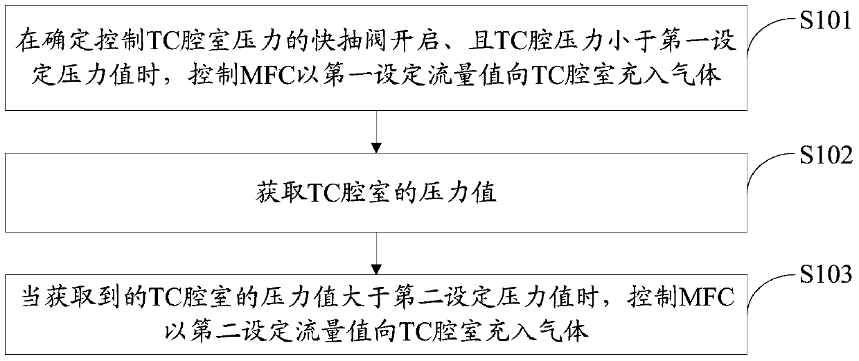
[0028] refer to figure 2 , shows a flow chart of the steps of a pressure control method in Embodiment 1 of the present invention.

[0029] The pressure control method of the present embodiment includes the following steps:

[0030] Step S101: When it is determined that the pumping valve controlling the pressure of the TC chamber is open and the pressure of the TC chamber is lower than the first set pressure value, control the MFC (Mass Flow Controller, mass flow controller) to the TC with the first set flow value The chamber is filled with gas.

[0031] Wherein, the pumping valve includes a slow pumping valve and a fast pumping valve, and the MFC is a device installed outside the TC chamber for charging gas into the TC chamber, and the device can also control the flow rate of the gas being charged. This application does not specifically limit how and where the MFC is installed outside the TC chamber. At the same time, those skilled in the art should understand that there i...

Embodiment 2

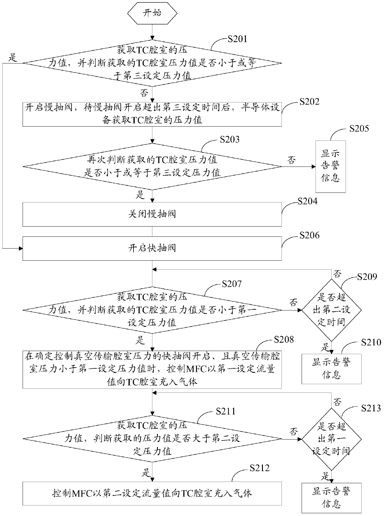
[0044] refer to image 3 , shows a flow chart of the steps of a pressure control method in Embodiment 2 of the present invention.

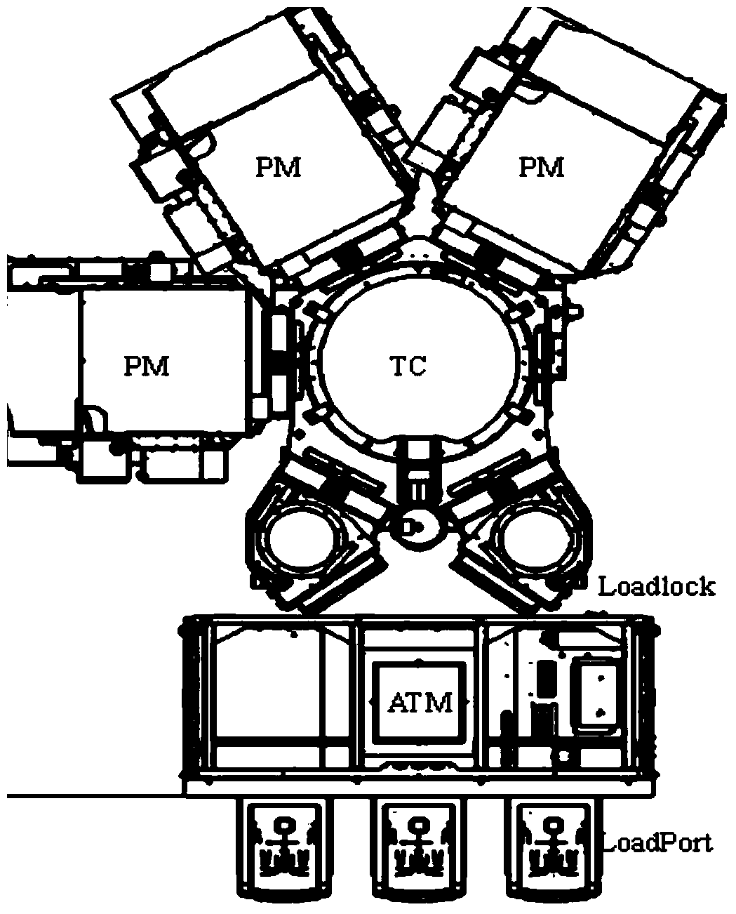
[0045] In this embodiment, in order to solve the problem that the PM chamber emits residual gas to the TC chamber during the process of transferring wafers between the PM chamber and the TC chamber in the existing semiconductor equipment, a simultaneous control method for the TC chamber and the PM chamber is adopted. The method of pressure means that when the machine is in normal state, the pressure of the PM chamber is controlled within a certain range, while the pressure of the TC chamber is slightly greater than the pressure of the PM chamber. In the implementation process, the existing TC chamber needs to be improved, and an MFC is added outside the TC chamber to input gas (such as high-purity N 2 , and at the same time open the quick pumping valve to realize the dynamic balance of the pressure in the TC chamber.

[0046] The structure of th...

Embodiment 3

[0083] refer to Figure 5 , shows a structural block diagram of a pressure control device according to Embodiment 3 of the present invention.

[0084] The pressure control device in this embodiment is set on the semiconductor device, and specifically includes: a first control module 501, which is used to determine that the pumping valve controlling the pressure of the vacuum transmission chamber is opened, and the pressure of the vacuum transmission chamber is lower than the first setting pressure value, control the mass flow controller to fill the vacuum transfer chamber with gas at the first set flow rate; the acquisition module 502 is used to obtain the pressure value of the vacuum transfer chamber; the second control module 503, When the pressure value acquired by the acquisition module is greater than a second set pressure value, control the mass flow controller to fill the vacuum transfer chamber with gas at the second set flow rate, wherein the first A set flow value i...


PUM


Abstract

The invention provides a pressure control method and device. The pressure control method comprises the steps of determining an extraction valve for controlling pressure of a vacuum transmission chamber to start, and controlling a mass flow controller to charge a gas to the vacuum transmission chamber with a first set flow value when the pressure of the vacuum transmission chamber is smaller than a first set pressure value; acquiring a pressure value of the vacuum transmission chamber; and controlling the mass flow controller to charge the gas to the vacuum transmission chamber with a second set flow value when the acquired pressure value is larger than a second set pressure value, wherein the first set flow value is larger than the second set flow value. With a pressure control scheme provided by the embodiment of the invention, the pressure recovery time of a TC chamber can be effectively shortened, so that the chip transmission efficiency between the TC chamber and a PM chamber is improved.

Description

technical field [0001] The invention relates to the technical field of semiconductors, in particular to a voltage control method and device. Background technique [0002] In semiconductor equipment, wafer processing is often carried out in a process chamber in a high vacuum environment. Refer below figure 1 The process of wafer processing is described by taking a plasma etching machine as an example. Such as figure 1 As shown, usually an etching machine with a high degree of automation is divided into three vacuum chambers according to the function: the process chamber is the PM chamber, the vacuum transfer chamber is the TC chamber, and the vacuum lock chamber is the Load Lock chamber. Isolation valves are installed between chambers with different functions to ensure mutual independence and vacuum. [0003] During normal operation, the PM chamber and the vacuum transmission chamber are always in a high vacuum state, while the Load Lock chamber needs to be constantly swi...

Claims


Application Information

Patent Timeline
Patent Type & Authority Patents(China)
IPC IPC(8): H01L21/67H01L21/677
CPCH01L21/67253H01L21/67739
Inventor 毕会杰李娟娟
Owner BEIJING NAURA MICROELECTRONICS EQUIP CO LTD
Why Eureka
Try Eureka