Stator base for three-degree-of-freedom spherical rotor ultrasonic motor

A spherical rotor, ultrasonic motor technology, applied in generators/motors, piezoelectric effect/electrostrictive or magnetostrictive motors, electrical components, etc., can solve problems such as insufficient driving capacity, complex structure, and insufficient driving feet. , to achieve the effect of simple structure, improved driving ability and mass production

Active Publication Date: 2017-03-22
HARBIN INST OF TECH
View PDF4 Cites 14 Cited by
  • Summary
  • Abstract
  • Description
  • Claims
  • Application Information

AI Technical Summary

Problems solved by technology

[0004] In order to solve the problems of the existing multi-degree-of-freedom rotary ultrasonic motor with few driving feet, insufficient driving capacity,

Method used


Image

  • Stator base for three-degree-of-freedom spherical rotor ultrasonic motor
  • Stator base for three-degree-of-freedom spherical rotor ultrasonic motor
  • Stator base for three-degree-of-freedom spherical rotor ultrasonic motor

Examples


specific Embodiment approach 1

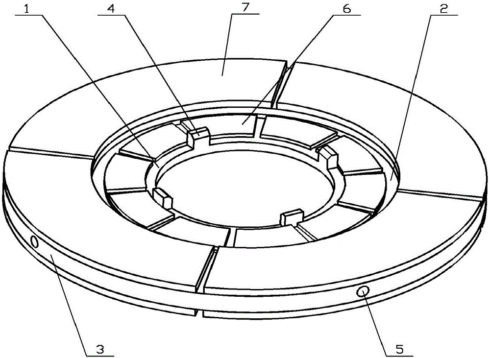
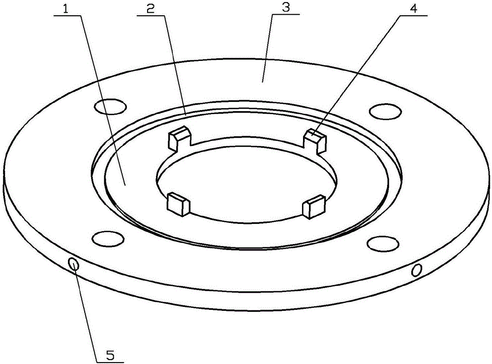
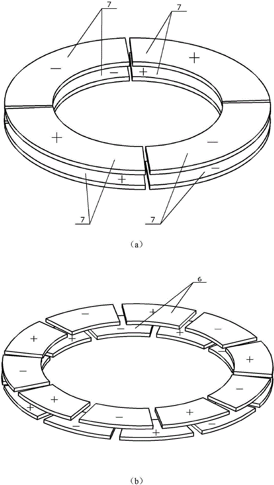
[0013] Specific implementation mode one: combine Figure 1 to Figure 4 Describe this embodiment. The stator base of the three-degree-of-freedom spherical rotor ultrasonic motor described in this embodiment includes an axial vibration ring 1, a vibration isolation ring 2, a radial vibration ring 3, four driving feet 4, and two sets of axial vibration rings. Ring piezoelectric ceramic sheet group and two groups of radial vibration ring piezoelectric ceramic sheet groups; axial vibration ring 1, vibration isolation ring 2 and radial vibration ring 3 are coaxially arranged; wherein axial vibration ring 1 and radial vibration ring 3 is connected through the vibration isolation ring 2 in the middle; the upper surface of the axial vibration ring 1 is arranged with four driving feet 4 along the circumferential direction; the upper and lower surfaces of the axial vibration ring 1 are respectively fixed with a group of axial vibration ring piezoelectric ceramics Sheet group, each axial ...

specific Embodiment approach 2

[0015] Specific Embodiment 2: This embodiment is a further limitation on the stator base of the three-degree-of-freedom spherical rotor ultrasonic motor described in Embodiment 1. In this embodiment, the axial vibration ring 1, the vibration isolation ring 2 and the radial vibration ring 3 in one piece. The axial vibration ring 1 is located inside the vibration isolation ring 2, the radial vibration ring 3 is located outside the vibration isolation ring 2, and the vibration isolation ring 2 is located in the middle, and its thickness is smaller than that of the axial vibration ring 1 and the radial vibration ring 3. This arrangement can make the axial vibration of the axial vibration ring 1 not have a great influence on the radial vibration of the radial vibration ring 3, and at the same time, the radial vibration of the radial vibration ring 3 can be effectively coupled to the internal driving foot Above all, the axial vibration of the axial vibration ring 1 and the radial vi...

specific Embodiment approach 3

[0016] Specific Embodiment 3: This embodiment is a further limitation of the stator base of the three-degree-of-freedom spherical rotor ultrasonic motor described in Embodiments 1 and 2. In this embodiment, four driving feet 4 are evenly arranged, that is, two adjacent driving legs 4 The spatial phase difference between the feet is 90°.

[0017] Such an arrangement is conducive to forming an elliptical driving track with a higher amplitude, and at the same time, the symmetrical driving feet are beneficial to improving the stability of the stator base.


PUM


Abstract

The invention provides a stator base for a three-degree-of-freedom spherical rotor ultrasonic motor, relates to the three-degree-of-freedom spherical rotor ultrasonic motor, and aims at solving the problems that an existing multi-degree-of-freedom rotary ultrasonic motor is insufficient in drive capability and complicated in structure, and miniaturization is difficult to implement. An axial vibration ring, a spacer ring and a radial vibration ring are coaxial, and the axial vibration ring and the radial vibration ring are connected through the middle spacer ring; the upper surface of the axial vibration ring is provided with four drive feet; ten piezoelectric ceramic pieces are fixed on each of the upper surface and the lower surface of the axial vibration ring, a space phase difference between two groups of piezoelectric ceramic pieces is 18 degrees and two adjacent piezoelectric ceramic pieces in each group are opposite in polarization direction; four piezoelectric ceramic pieces of the radial vibration ring are fixed on each of the upper surface and the lower surface of the radial vibration ring, the space phase difference between two groups of piezoelectric ceramic pieces is zero degrees and two adjacent piezoelectric ceramic pieces in each group are opposite in polarization direction; and all piezoelectric ceramic pieces are polarized along the thickness direction. The stator base for the three-degree-of-freedom spherical rotor ultrasonic motor is suitable for the three-degree-of-freedom spherical rotor ultrasonic motor.

Description

technical field [0001] The invention relates to a three-degree-of-freedom spherical rotor ultrasonic motor stator base, belonging to the technical field of piezoelectric ultrasonic motors. Background technique [0002] Piezoelectric ultrasonic motor is a kind of piezoelectric ultrasonic motor that uses the inverse piezoelectric effect of piezoelectric ceramics to excite vibration in the ultrasonic frequency range in the elastic body, and forms a particle motion with a specific trajectory at a specific point or area on the surface of the elastic body, and then passes through the stator, The frictional coupling between the rotors converts the microscopic motion of the particle into the macroscopic motion of the rotor, which has the advantages of low speed and high torque, no need for a speed change mechanism, no electromagnetic interference, fast response, and self-locking when power is off. [0003] However, the existing multi-degree-of-freedom rotary ultrasonic motors have p...

Claims


Application Information

Patent Timeline
IPC IPC(8): H02N2/12H02N2/10
CPCH02N2/108H02N2/12
Inventor 石胜君熊怀银陈维山刘英想刘军考
Owner HARBIN INST OF TECH
Why Eureka
Try Eureka