A self-triggering discharge control circuit based on sbs

A discharge control and self-triggering technology, applied in the direction of electric pulse generator circuit, energy storage element to generate pulses, etc., can solve problems such as back-end circuit failure, reduce PCB board area, realize high and low voltage isolation, and high reliability Effect

Active Publication Date: 2019-12-24
天津航空机电有限公司
View PDF4 Cites 0 Cited by
  • Summary
  • Abstract
  • Description
  • Claims
  • Application Information

AI Technical Summary

Problems solved by technology

The ignition device adopts thyristor discharge circuit, its main transformer basically has three windings, primary winding, secondary winding and feedback winding, wherein the feedback winding is used to trigger the energy storage of thyristor pulse, the trigger signal is controlled by the front-end control circuit, once the control circuit Failure, easy to cause back-end circuit failure

Method used


Image

  • A self-triggering discharge control circuit based on sbs
  • A self-triggering discharge control circuit based on sbs

Examples


Embodiment Construction

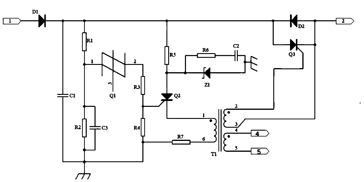
[0009] The technical solutions created by the present invention will be further described in conjunction with the accompanying drawings and specific embodiments.

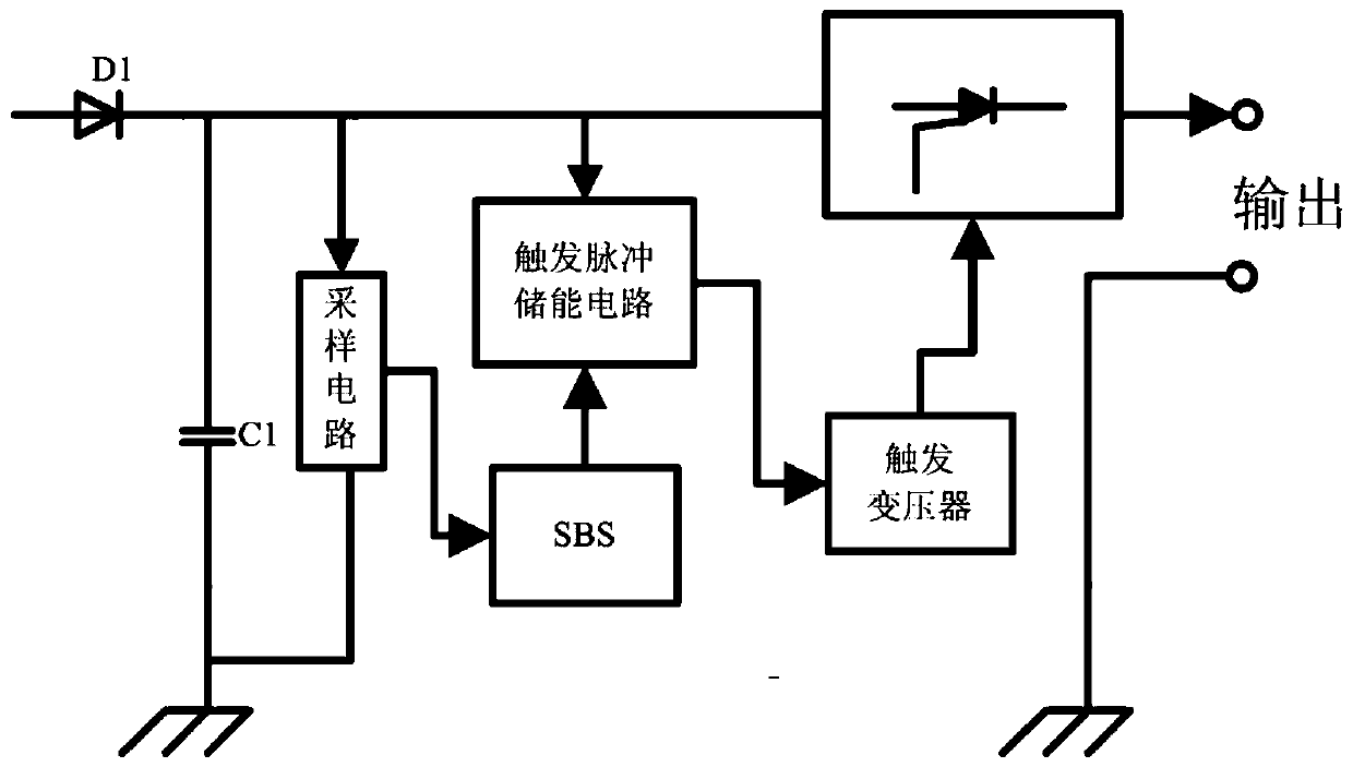
[0010] like figure 1 As shown, capacitor C1 is an energy storage capacitor, and a voltage divider circuit composed of resistors R1 and R2. The upper end of resistor R2 is connected to pin 1 of silicon bidirectional switch Q1, and pin 2 of silicon bidirectional switch Q1 is connected to the gate of thyristor Q2 through resistor R3. Resistor R5, resistor R6, and capacitor C2 form a trigger energy storage circuit, the regulator Z1 is connected in parallel with the resistor R6 and capacitor C2, the cathode of the regulator Z1 is connected to the A pole of the thyristor Q2, and the K of the thyristor Q2 The pole contacts pin 1 of the trigger transformer T1, pin 6 of the trigger transformer T1 is grounded; pin 2 of the trigger transformer T1 is connected to the gate of the thyristor Q3, pin 3 of the trigger transformer is...


PUM


Abstract

The present invention belongs to the technical field of electrical control, and relates to a discharge control circuit of a pulse apparatus and particularly relates to a silicon bidirectional switch (SBS)-based self-triggered discharge control circuit. The circuit is based on an SBS. Partial pressures of a resistor R1 and a resistor R2 are set through a turning voltage of the silicon bidirectional switch. When the voltage of the resistor R2 reaches the turning voltage of the silicon bidirectional switch, Q1 of the silicon bidirectional switch is connected instantly, the silicon bidirectional switch triggers Q2 to be connected, a primary level of a trigger transformer T1 is triggered, a secondary level senses a corresponding pulse, a thyristor Q3 is triggered to be connected, and then discharge output is completed. The circuit can realize self-triggered discharge without using a control signal of a front end circuit. The SBS (silicon bidirectional switch) is combined with controllable silicon, and a certain value of resistor and capacitor are configured, so that the self-triggered discharge circuit is formed. The SBS-based self-triggered discharge control circuit can adjust energy storage voltage accurately, uses a semiconductor part, and has a long service life, high reliability, and high anti-interference capability. The present invention provides a novel discharge control circuit for the pulse apparatus.

Description

technical field [0001] The invention belongs to the technical field of electrical control, and relates to a pulse device discharge control circuit, in particular to a SBS-based self-trigger discharge control circuit. Background technique [0002] The ignition device, which is an important part of the engine ignition system, is a pulse generator. The ignition device has developed from the gas discharge tube type to the semiconductor thyristor type ignition device. The discharge frequency of the ignition device is divided into variable voltage variable frequency type and variable voltage fixed frequency type. The discharge circuit currently used in the ignition device basically adopts a discharge tube discharge and a discharge circuit based on a thyristor. The discharge tube is discharged by the method of breakdown gas. The gas is radioactive, and the glass package is fragile. Protective measures must be taken during installation. The ignition device adopts thyristor discha...

Claims


Application Information

Patent Timeline
Patent Type & Authority Patents(China)
IPC IPC(8): H03K3/57
CPCH03K3/57
Inventor 冯建昌赵军闫东东王哲
Owner 天津航空机电有限公司
Why Eureka
Try Eureka